


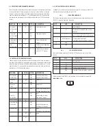
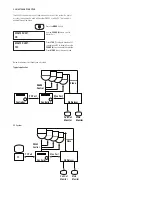

1.6 CONNECTIONS
There are five connectors on the VLC485 Controller. These connectors are a 9-pin
connector for RS232 connections to a PC, a 9-pin connector for RS232 connections to
an external device, a 4-pin compression connector for the RS485/422 pan/tilt network,
and a 9-pin terminal for alarm inputs. The RS232 ports are configured as data com-
munication equipment (DCE) ports.
1. Multiplexer Connector: (Not Supplied)
2. PC Connector: (Not Supplied)
Pin DCE Function
1
2 Transmit (to PC)
3 Receive (from PC)
4
5 Signal Ground
6
7
8
9
3. Multiplexer Connector: (Included)
Pin Function
1 Alarm 1 input
2 Alarm 2 input
3 Alarm 3 input
4 Alarm 4 input
5 Alarm 5 input
6 Alarm 6 input
7 Alarm 7 input
8 Alarm 8 input
9 Alarm Common
10 Alarm Output NO Contact
11 Alarm Output NO Contact
12 Alarm Output Common
4. Pan/Tilt Network Connector: (Included)
Pin Function
1 TXA to pan/tilts
2 TXB to pan/tilts
3 RXA from pan/tilts
4 RXB from pan/tilts
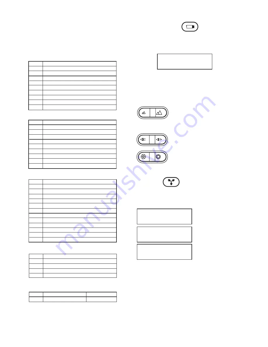
2.0 CONTROL OF THE BASIC FUNCTIONS
2.1 CAMERA SELECTION
In order to view or control a camera and the pan/tilt, the camera must be selected. To
do this, enter the camera number using the keypad and press the
CAMERA
button.
The LCD should show the following:
2.2 PAN/TILT MOVEMENT
Pan/tilt movement is controlled by the joystick. If the selected pan/tilt supports variable
speed operation the speed of the pan/tilt will be increased as the joystick is moved
away from the center position.
2.3 CAMERA ZOOM/FOCUS/IRIS FUNCTIONS
CAM 01
Use the
ZOOM OUT/ZOOM IN
key to operate the zoom
function of a selected camera.
NOTE:
Whenever the camera zoom is changed, the
controller places the camera into auto focus and auto iris
mode if these modes are available.
If you want to focus a camera manually press the
FOCUS
FAR/FOCUS NEAR
keys.
The
IRIS CLOSED/IRIS OPEN
keys will allow you to
change the iris setting of a camera.
NOTE:
Some cameras provide continuous iris function as
the keys are held down; others may require repetitive key
presses.
2.4 PRESETS
For pan/tilts that support presets, up to 99 can be programmed on the VLC485. To
LOCKOUT presets, see Menu Section, Item 3.3.
TO SET A PRESET:
CAM 01
CAM 01
CAM 01
07
PRESET 07
Select a camera and position it to the
desired location.
Enter the preset number (1 - 99) on the
keyboard.
Press the
POUND (#)
key, then press
the PRESETS key.
TO GO TO A PRESET: Select the camera as noted above. Enter the preset number.
Press the
PRESET
button and the camera will go to the preset location. The LCD will
show the camera number and preset number as shown above.
TO CLEAR A SINGLE PRESET: Select the camera as noted above. Enter the preset
number, press the
STAR (*)
key, then press the
PRESET
button.
For errors or to change the preset number repeat the procedure.
5. Power 5VDC: (Included)
1 Center Contact
+ (Plus)
2 Outside Contact
- (Minus)
Pin DCE Function
1
2 Transmit data (to main multiplexer)
3 Receive data (from main multiplexer)
4
5 Signal Ground
6
7
8 Signal Ground
9 Transmit data (to expansion multiplexer)
TO CLEAR ALL PRESETS: Select the camera as noted above. Press the
STAR (*)
key,
then press the
PRESET
button. A "?" will appear. Press PRESET again and all presets
for that camera will be cleared. To cancel this function, press the
STAR (*)
key.


