Moog Videolarm QSDP Скачать руководство пользователя страница 6

-  -

CAMERA ADJUSTMENT

1.  Access the cameras by removing the dome. Loosen the locking
     screws on the lip of the dome. DO NOT TAKE THESE SCREWS 
     OUT. Once the screws are loosened, turn the dome counter 

clockwise until it stops, then pull the dome off. 

CAMERA FOCUSING (FOR EACH CAMERA)


Fixed Lens:

  Loosen the set screw in the lens mount. Manually

                           rotate the lens until a clear picture is achieved. Once
                           the focus is set, retighten the set screw (Figure 5).

Figure 5

Set screw

Fixed lens

Auto Iris Lens:  

NOTE:  THE AUTO IRIS LENS IS SET AT THE FACTORY. 

             • IF YOU EXPERIENCE VIDEO TOO LIGHT OR DARK 
               AUTO IRIS ADJUSTMENT MAY BE NEEDED.


SEE THE TROUBLESHOOTING SECTION FOR 

             ADJUSTMENT INFORMATION.

CAMERA SETTINGS

HIGH-RES BLACK & WHITE

FIXED AND FIXED VARI-FOCAL LENSES. There are no user 
adjustable settings on these units (Figure 7).

Figure 7

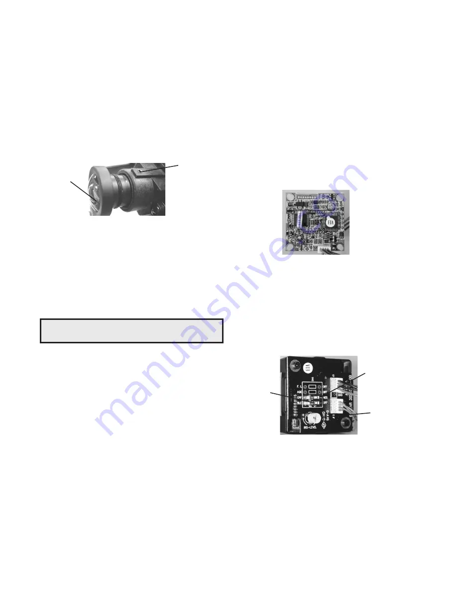
AUTO IRIS LENSES. The dip switches are factory set with AES 
off and backlight compensation on (Figure 8). The auto iris is also 
set at the factory, but an adjustment screw is included for use if 
needed. See page 10 for instructions on adjusting Auto Iris.

Auto Iris
adjustment 
screw

AES Default Off

Backlight 
Compensation 
Default On

Figure 8

BW Fixed and Vari-Focal

BW Auto Iris

NOTE:

 To determine which camera is used in your unit, locate the 

            serial number on the inside of the housing. Match the two 
            letter prefix with the corresponding instructions included 
            here for adjustments.

Содержание QSDP

Страница 1: ...Before attempting to connect or operate this product please read these instructions completely Product Instructions QView Series QSD Outdoor Dome QSDW QSDP 81 IN5362 12 8 05...

Страница 2: ...charges The limited warranty stated in these product instructions is subject to all of the following terms and conditions 1 NOTIFICATION OF CLAIMS WARRANTY SERVICE If Purchaser believes that the Produ...

Страница 3: ...l with 4 bolts not provided NOTE Be sure the hardware and the mounting surface can support the weight of the wall mount bracket plus the weight of the housing and drive unit The load will be subjected...

Страница 4: ...24 VAC Yellow 4 Accessory Power 24 VAC Green POWER 4 Attach the wires from the wall to the connector provided using the wiring color code chart as a guide 5 Once all wiring connections are made place...

Страница 5: ...meters The QRH is setup with 2 individual power inputs 1 Accessory Power yellow and green wire 2 Camera Power red and orange If you wish to provide a single power transformer it is recommended that 1...

Страница 6: ...MAY BE NEEDED SEE THE TROUBLESHOOTING SECTION FOR ADJUSTMENT INFORMATION CAMERA SETTINGS HIGH RES BLACK WHITE FIXED AND FIXED VARI FOCAL LENSES There are no user adjustable settings on these units Fi...

Страница 7: ...ve the option of transmitting video signals to NVT receivers via unshielded twisted pair cable You must purchase the receiver separately Instructions for connecting the receiver end of the the unshiel...

Страница 8: ...DO make sure the pair of wires carrying the video signal is sent as a twisted pair e g the blue white white blue wires twisted together as a pair not a split pair e g blue white conductor part of one...

Страница 9: ...k polarity WON T SYNC TORN PICTURE 1 Make sure that you are using unshielded twisted pair wire 2 Check distance equalization settings 3 For installations with passive non amplified transceivers at bot...

Страница 10: ...ppear to be unusually dim STATIONARY OR SCROLLING HORIZONTAL LINES ON SCREEN PICTURE IS CLEAR LOW OR NO COLOR PICTURE IS DARK OR GRAINY IN GOOD LIGHTING CONDITIONS The auto iris lens is set at the fac...

Страница 11: ...11 2 000 3 250 R 733 2 132 2 981 1 537 5 500 Mounting Template...

Отзывы: