Moog Videolarm IP ReadyTM Series Video Alarm FDW75C12N Скачать руководство пользователя страница 21

-  -

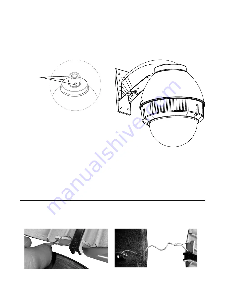
3.  Mount the housing assembly to the mounting bracket 

and housing coupling.  A safety cable is included with 
the housing to temporarily hold it while making wiring 
connections.  Loop the safety cable over one of the set 
screws on the housing coupling  and make the appropriate 
connections using the (2) screw-down connectors supplied.

4.  Undo the safety cable and twist the housing onto the 

housing coupling.  Secure all (3) setscrews provided on the 
housing coupling.

Set screws

INSTALLING WALL MOUNT

A wall mount bracket comes standard with this unit, and 
a template is included to use as a guide for mounting the 
bracKet to a wall.


1.  Choose the desired location for installation and mark 

the drill holes using the template. Screw (2) bolts (not 
provided) about ¾ of the way into the (2) top holes. Run 
approximately 8 of wiring out of the wall.

NOTE:


Be sure the hardware and the mounting surface 
can support the weight of the wall mount bracket 
plus the weight of the housing and drive unit. 
The load will be subjected to vibration from the 
camera motor and wind. 

2.  The wall mount bracket provided with the FDW7 includes 

a location for conduit entry. If you wish to install conduit to 
the bracket remove the conduit hole plug. Install fitting from 
below the wall mount and secure with conduit nut from 
inside the bracket.

3.  Open the access door on the bottom of the wall mount by 

loosening the screw nearest the mounting plate.

4.  Attach the wires from the wall to the connector provided. 

using the wiring color code chart as a guide.

5.  Once all wiring connections are made, place the wires 

inside the wall mount bracket and close the access door. 
Secure with the screw removed earlier.

Access panel

CONNECTING THE TRIM RING ASSEMBLY TO THE 

HOUSING TOP:

1.  Open the access door on the bottom of the wall mount by 

loosening the screw nearest the mounting plate.

2.  There is a safety lanyard that is attached to the inside of 

the dome assembly.  Take the open end of the lanyard and 
loop it around the lanyard tab that is located inside the 
housing top.

3.  The safety lanyard is now attached to the housing.

Содержание IP ReadyTM Series Video Alarm FDW75C12N

Страница 1: ...Before attempting to connect or operate this product please read these instructions completely Product Instructions IP Ready Series FDW75C12N FDP75C12N 81 IN5329 04 28 06...

Страница 2: ...charges The limited warranty stated in these product instructions is subject to all of the following terms and conditions 1 NOTIFICATION OF CLAIMS WARRANTY SERVICE If Purchaser believes that the Produ...

Страница 3: ...IP Ready Network Housing with 12Vdc input wall mount or pendant mounting heater blowers ready for standard IP PTZ cameras ASSEMBLING THE UNIT Remove content from all boxes Contents should include Mai...

Страница 4: ...cameras See specific instruction for the model that matches the unit you have INDEX OF CAMERAS AXIS 213 5 AXIS 214 6 CANON VB C10R 7 CANON VB C50iR 8 CANON VC C4R VC C50iR 9 ELMO PTC 200C 10 ELMO PTC...

Страница 5: ...ng Use 4 2 spacer s plus 4 1 spacer s and 4 spacer s provided in the 2 hardware packets Attach camera using these 2 holes 1 2 Captive Screw 3 screws in housing 3 Place 3 8 x 32 x s Phillips head screw...

Страница 6: ...2 The AXIS 214 camera requires 2 of spacing for optimal position within the housing Use the 4 2 spacers provided in the packet 3 Place 3 8 x 32 x s Phillips head screws on the top of the spacer as sho...

Страница 7: ...ousing Use 4 2 spacer s plus 4 1 spacer s and 4 spacer s provided in the 2 hardware packets Attach camera using these 2 holes 1 2 3 Place 3 8 x 32 x s Phillips head screws on the top of the spacer as...

Страница 8: ...housing Use 4 2 spacer s plus 4 1 spacer s and 4 spacer s provided in the 2 hardware packets Attach camera using these 2 holes 1 2 3 Place 3 8 x 32 x s Phillips head screws on the top of the spacer a...

Страница 9: ...on within the housing Use 4 2 spacer s plus 8 1 spacer s provided in the 2 hardware packets Attach camera using these 2 holes 1 2 3 Place 3 8 x 32 x s Phillips head screws on the top of the spacer as...

Страница 10: ...before proceeding 2539 Mounting Plate 1 Place the camera onto the quick release bracket using the 4 metric 3M Phillips head screws provided with the kit Attach camera using these 4 holes 1 2 2 The El...

Страница 11: ...s provided with the kit Attach camera using these 4 holes 2 2 The Elmo PTC 201 camera requires 2 of spacing for optimal position within the housing Use 4 2 spacer s plus 4 spacer s provided in the 2 h...

Страница 12: ...with the kit Attach camera using these 4 holes 1 2 2 The Elmo PTC 400C camera requires 3 5 of spacing for optimal position within the housing Use 4 2 spacer s plus 4 1 spacer s and 4 spacer s provided...

Страница 13: ...1C Attach camera using these 4 holes 2 2 In the packet there will be a number of 2 inch and 1 inch spacers Take four of the 1 inch spacers and screw them onto the spacers that are on the base bracket...

Страница 14: ...umber of 2 inch and inch spacers Take four of the inch spacers and screw them onto the spacers that are on the base bracket to make a 2 inch spacer Place two 8 32 X s Philips head screws on the two an...

Страница 15: ...her provided 2 The Panasonic BB HCM381 KX HMC280 requires 3 of spacing to properly position the camera within the housing 3 Place 3 8 x 32 x s Phillips head screws on the top of the spacer as shown ab...

Страница 16: ...of spacing to properly position the camera within the housing Use 4 spacers provided in the hardware packets 3 Place 3 8 x 32 x s Phillips head screws on the top of the spacer as shown above Be sure t...

Страница 17: ...properly position the camera within the housing Use 4 2 spacers provided in the hardware packets 3 Place 3 8 x 32 x s Phillips head screws on the top of the spacer as shown above Be sure to place the...

Страница 18: ...position the camera within the housing Use 4 2 spacers plus 4 spacers provided in the hardware packet 3 Place 3 8 x 32 x s Phillips head screws on the top of the spacer as shown above Be sure to plac...

Страница 19: ...uires 3 of spacing to properly position the camera within the housing Use 4 2 spacers plus 4 1 spacers provided in the hardware packets 3 Place 3 8 x 32 x s Phillips head screws on the top of the spac...

Страница 20: ...Alarm 2 Violet 3 Alarm 3 Gray 4 Common White Be sure the bracket is properly and securely mounted to a supporting structure capable of rigidly holding the weight of the entire unit INSTALLING THE HOUS...

Страница 21: ...weight of the housing and drive unit The load will be subjected to vibration from the camera motor and wind 2 The wall mount bracket provided with the FDW7 includes a location for conduit entry If yo...

Страница 22: ...22 Exploded View for Replacement Parts 1 11 6 9 10 1 1 1 2 3 5 4 7 8 14 16 6 12 13 18 1 1 3 2 2 2 8 4 2 1 1 4 4 1 3 4 3 3 1 1 4 4 1 1 4 4 19 17 1 1 2 Not included on 12Vdc housings...

Страница 23: ...LS 24VAC ONLY 8 RPFD040 HOUSING HARDWARE 9 RPFD709 HOUSING TOP 10 RPFD2612 HOUSING TOP GASKET 11 WM10 WM10 WALL MOUNT 12 RPNET02 NETWORK HOUSINGS POWER BOARD NOT INCLUDED ON 12VDC UNITS 13 RPNET04 NET...

Страница 24: ...24 2 000 3 250 R 733 2 132 2 981 1 537 5 500 Mounting Template...

Отзывы: