background image

Page 28

H*38DF PFC Peninsula Gas Fireplace

XG0816 - 150204.1

Operation

Operation

To Turn Off  Gas To Appliance:

3.  Push in gas control knob slightly and turn  

  clockwise to 

"Off".  Do not force.

4.  Replace the lower Horizontal access panel.

1.  Turn off remote switch.
2.  Lift out the lower Horizontal access panel

.

Lighting Instructions:

1�


STOP!


Read the safety information above on this label.

2�

  Lift out the lower Horizontal access panel

.

3�

  Push in gas control knob and turn clockwise 

  to "OFF."

4�

  Wait  five  (5)  minutes  to  clear  out  any  gas.  Smell  for  gas, 

including near the floor. If you then smell gas, 

STOP!

 Follow 

"B" in the safety information above on this label. If you don't 

smell gas, go to the next step.

5�

  Locate pilot burner 

(See illustration at right.)

 and follow steps 

below.

6�

  Turn knob on gas control counter clockwise  

  to "PILOT."

7�

  Push in gas control knob completely and hold. Light with Piezo 

Igniter button. Continue to hold the control knob in for about 

(1) minute after the pilot is lit. Release the knob and it will pop 

back up. Pilot should remain lit. If it goes out repeat steps 3 

through 8.


„

If knob does not pop up when released. Stop and immediately 

call your service technician or gas supplier.


„

If the pilot will not stay lit after several tries, turn the gas control 

knob to "OFF" and call your service technician or gas supplier.

8�

  Push in gas control knob and turn 

counter-clockwise  

  to "ON."

9�

  Replace the lower Horizontal access 

panel.

10� 

Turn on remote switch to ignite fire.

NOTE: 

Gas control knob cannot be turned from  "PILOT" to "OFF" 

unless knob is pushed in slightly.  Do not force.

Standing (Continuous)  Pilot Ignition


(SIT NOVA 820)

with American Flame Electronic Ignition

For Your Safety - READ BEFORE LIGHTING:

SIT Proflame 2 Electronic Ignition

„

  If you cannot reach your gas supplier, call the Fire Depart-

ment.

C.  Use only your hand to push in or turn the gas control knob. Never 

use tools. If  the knob will not push in or turn by hand, don't try to 

repair it, call a qualified service technician. Force or attempt to 

repair may result in a fire or explosion.

D.  Do not use this appliance if any part has been under water. 

Immediately call a qualified service technician to inspect the 

appliance and to replace any part of the control system, and any 

gas control which has been under water.

A.  This appliance is equipped with an ignition system that lights the 

pilot burner automatically. Do not attempt to light the pilot by hand.

B.  BEFORE LIGHTING smell all around the appliance area for gas.  

Be sure to smell next to the floor because some gas is heavier 

than air and will settle on the floor.

  What To Do If You Smell Gas:

„

  Do not try to light any appliance.

„

  Do not touch any electrical switch; do not use any phone in 

your building.

„

  Immediately call your gas supplier from a neighbour's phone. 

Follow the gas supplier's instructions.

If the information in these instructions is not followed exactly, a fire or explosion may 

result causing property damage, personal injury or death.

WARNING

WARNING/ CAUTION:  Hot while in operation.  Do not touch.  

Severe burns may result.  Keep children, clothing, furniture, 

gasoline and other liquids having flammable vapours away.

See installation and operating instructions accompanying this 

appliance.

Lighting Instruction Updates

Lighting Instruction Updates

Lighting Instruction Updates

Lighting Instruction Updates    

Replace the warning label with danger label in the  

Replace the warning label with danger label in the  

Replace the warning label with danger label in the  

Replace the warning label with danger label in the  

Lighting instructions

Lighting instructions

Lighting instructions

Lighting instructions    


Содержание H38DF PFC

Страница 1: ...anger overhead crane Explosion risk Oxidising Danger of death Biohazard Laser Radiation Danger of entrapment Hot surface General Warning Blank Gas bottles Watch for falling objects Electricity Danger for cutter Entrapment hazard Battery hazard Rotating parts Low temperature Strong magnetic field Optical radiation Non ionizing radiation Radiation Hazardous to the Environment Danger of harming your ...

Страница 2: ...ALLING A WALL MOUNTED DIRECT VENT TERMINATION 12 Section 3 3 1 VENTING LAYOUT Wall mounted termination 13 Section 3 3 2 VENTING COMPONENTS 17 Section 3 3 3 Heat Shields 18 Section 4 Wiring 19 Section 5 1 FUEL CONVERSION 20 Section 5 2 GAS PRESSURE 20 Section 5 3 GAS CONNECTION 20 Section 5 Installing the Gas Line 20 Section 6 Finishing Around the Fireplace 21 Section 7 Screen Installation and Remo...

Страница 3: ...ualisapplicable to the models described below Refer to your rating plate to verify included options Throughout this manual instructions are applicable to all models designated as H 38PF unless otherwise noted in the Table Warranty Information See Appendix B The Montigo warranty will be VOIDED by and Montigo disclaims any responsibility for the following actions Modification of the fireplace and or...

Страница 4: ...he absenceoflocalcodestothecurrentversionofNaturalGasandPropane Installation Code CSA B149 Electrical Installations must conform to the local codes or in the absence of local codes to the current version of Canadian Electrical Code CSA C22 1 1 Installations in the USA must conform to the local codes or in the absence of local codes to the current version of National Fuel Gas Code ANSI Z223 1 NFPA ...

Страница 5: ...Installation Rating Plate Sample LB1223 V5 0 SIT IPI with screen JUN 16 2014 Teklynx LabelView Demo LBL1205 V6 1 Stand Pilot Screen DEC06 2014 Teklynx LabelView Demo Figure A Rating Plate for IPI eletronic ignition Figure B Rating Plate for standing pilot SIT ...

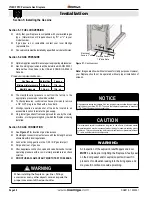
Страница 6: ...oningducts electricalwiringandplumbing Safety as well as efficiency of operation should be considered when selecting the fireplace location Select a location that does not interfere withroomtraffic hasadequateventilationandoffersanaccessiblepath for Direct Vent installation Figure 1 Fireplace dimensions with Nailing Flange Extension shown Tolerance The fireplace dimensions are shown below Top View...

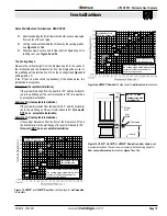
Страница 7: ... Framing dimensions Figure 3 Combustible Framing for shelves over the fireplace Rear vent Figure 5 Non Combustible Framing with alcove above fireplace Top Vent 41 23 3 4 44 Figure 4 Combustible Framing for shelves over the fireplace Top vent 11 Min Combustible Shelf 33 44 Exterior Wall Combustible Header 12 Max 4 Nailing flange or Non combustible material 46 Min 17 1 2 2 Min 44 Combustible Shelf C...

Страница 8: ...F Series gas fireplaces are required to have the supplied standoffs installed The fireplace is supplied with two standoffs Bend and install these standoffs on top of the fireplace ensuring that the height of the standoff maintains a 8 clearance Note Clearance from top of fireplace to a ceiling within the fireplace enclosure 8 Fasten Standoffs in gutter Figure 6 Installing the standoff s Nailing Fl...

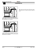
Страница 9: ...ation location MUST be selected such that it is the highest point in the venting assembly It should also be selected such that it provides the shortest vent run possible Should it be impossible to ensure that the termination is the highest point or should it be impossible to meet the venting guidelines laid out below please contact your Montigo dealer to discuss power venting options NOTES FOR PLA...

Страница 10: ... of allowed termination locations see Appendix A Termination location must be a minimum 6 from a mechanical air inlet A maximum of two offsets each offset is made up of 2 90 bends may be made for vertical vent runs FirestopsmustbeinstalledasrequiredbyNational localcodes Ensure all horizontal runs are supported with a minimum of 3 supports per 10 of venting Install all roof flashing and storm colla...

Страница 11: ...Installation Note Imagesareshownwithoutscreensforclaritypurposes However your fireplace should not be operated without proper installation of screens Figure 9c Rear vent Roof mounted venting 1 90 bend Support ring Support plate 32 Ma x PVTK1 Termination 12 Max ...

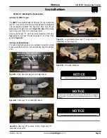
Страница 12: ...Frame the BSR opening to 12 x 12 2 Secure the BSR Frame to the exterior sheathing of the structure 3 FastentheterminationtotheBSRFrameusingaminimumof4screws 1 Frame the MOSR opening to 12 x 12 2 Fasten the MOSR frame to the interior side of the studs concrete or finished wall construction using a minimum of 4 screws 3 Insert the termination into the MOSR frame as shown here from the inside and att...

Страница 13: ... 12 Section 3 3 1 VENTING LAYOUT Wall mounted termination Selection of components and details of venting layout should adhere to the following guidelines Vent terminations must not be recessed in walls or siding For Heat Shield requirements see Section 3 3 3 Once the proposed venting layout has been determined refer to Figure 12 13 14 or 14a to ensure the layout is acceptable Notes Wall Mounted Te...

Страница 14: ...F Top Vented wall mounted Multi elbowinstallation SeeVentingGraphforTopvent wallmountedterminations Figure 12 or 13 Solid Section Flex Section Hearth 150 Max Heat Shield Termination Exterior Wall Heat Shield Termination Exterior Wall 30 Max 126 Max Solid Section Flex Section Hearth Figure13b H38PF HL38PF orHP38PF TopVented wallmountedRetracted Multi elbow installation See Venting Graph for Top ven...

Страница 15: ...38 this would be an acceptable installation Example B Unacceptable Installation If the vertical dimension from the hearth is 60 and the horizontal run to the wall flange of the vent termination is 84 this would not be an acceptable installation Example C Unacceptable Installation If the vertical dimension from the floor of the fireplace is 72 and the horizontal run to the wall flange of the vent t...

Страница 16: ...unted Multi elbow termination installation The vent run must comply with the Venting Graph for Rear vent wall mounted terminations Figure 14a 42 Max 60 Min 12 Max 27 Min 33 Hearth Flex or Rigid Section Figure 15a H38PF or HL38PF Rear Vented wall mounted Multi elbow termination installation The vent run must comply with the Venting Graph for Rear vent wall mounted terminations Figure 14 42 Max 53 M...

Страница 17: ...antforareviewof ALL penetrations through exterior walls or the roof Montigo recommends the use of a flex section for the final pipe connected directly to the fireplace offering greater flexibility of installation and absorption of movement Firestops must be installed as required by National local codes Montigorecommendsthatallexteriorcornersandjointsbesealed with exterior caulking However we encou...

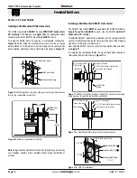
Страница 18: ... After the fireplace and vent pipe has been installed clearances should match the dimensions in Figure 16 Installing a Wall Mounted RHS101 Heat shield The RHS101 Heat shield MUST be used where the RHS8 Termination Figure 16 and 16a CANNOT be used Use the RHS101 within 36 horizontal or 60 vertical To install the RHS101 Slide the Inner Section over the vent pipe that will connect to the fireplace Fa...

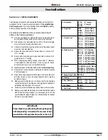
Страница 19: ...ts own power on a millivolt circuit Use only low voltagewire andNOTE Theswitchlocationmust not exceed 30 from the fireplace Figure 19 Wiring with SIT Nova 820 Models Included H38DFPFCN H38DFPFCL HL38DFPFCN HL38DFPFCL Manifold Pressure Test Connection Wall Switch Power Generator Pilot Adjustment Screw Inlet Pressure Hi Lo Adjustment Knob Gas Control Knob Shown in Pilot position Models Included H38D...

Страница 20: ...eplace Gas line and input system follow the appropriate local codes or your area DO NOT connect the fireplace to pressures in excess of 1 2lb This will damage the gas control valve NOTICE Note Imagesareshownwithoutscreensforclaritypurposes However your fireplace should not be operated without proper installation of screens WARNING An inspection of the explosion relief flappers and door MUST be mad...

Страница 21: ...rate this fireplace without the glass door or with a broken glass door NOTICE Do not use ammonia based or abrasive cleaners on the glass they will permanently etch the surface Use an approved gas fireplace glass cleaner such as Kel Kem or White off NOTICE WARNING We recommend careful consideration be given to the effects of elevated mantel temperatures which may be in excess of product design for ...

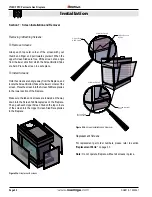
Страница 22: ... from which the Screen Bottom Tabs are held Place the screen in a safe place To Install Screens Holdthescreensatanangleawayfromthefireplace and locatetheScreenBottomTabsatthelowercornersofthe screen PlacethescreenintotheScreenTabReceptacles in the lower section of the fireplace Make sure the tabs and screens are lowered all the way down into the Screen Tab Receptacles on the fireplace Then push ea...

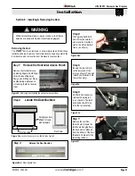
Страница 23: ... of the slot as shown Then pull toward you Caution hold the tool securely 3 Step 6 Pull hard if necessary to release the spring ten sion Caution The latch springs back with force hold the tool securely Figure 24d Figure 24e Front View Door buckles Small glass door affixed to frame with hardware Door Latch Hook Door Latch Slot Hand hold Release the Door Buckles Figure 24b Door buckle Tool 1 Step 4 ...

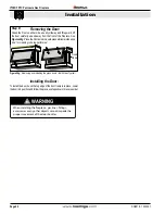
Страница 24: ...on either side usually midway and lift upward lift the door carefully up and away from the front of the fireplace See Figures24g PlacetheDoorasideinasafeplacewhilemaintenance and or cleaning is being performed Figure 24g Removing and installing the glass doors Both Sides Typical Removing the Door Fixed Panel WARNING When installing the fireplace gas lines fittings accessories or any other objects ...

Страница 25: ...supplied in two packages Spread the material evenly around the burner tray or pile around burner holes for a realistic effect Figure 25c Log Installation Place Logs C on top of Logs A Indentations on top of Logs A Figure 25b Place Logs B as shown in front of Right hand A and behind Left hand B Log A Log B Log C Log A Log C Figure 25d Completed Installation Figure 25 Empty firebox showing the Left ...

Страница 26: ...l Figure 26a Place Log A and B in the grate on either side of the burner Log A Log B Log D Log C Figure 26b Place Log C and D diagonally across Logs A and B Figure 26c Place Log E diagonally across Log C Ensure that log E does not touch the grate Log E Figure 26d Place log F into slot at the side of unit Log F Figure 26e Place log G diagonally across log D Log placement complete Log G Figure 26g E...

Страница 27: ...s and Propane Fireplaces The HL38PF fireplace is supplied with firestones Remove the Door as shown on page 21 Follow these instructions to ensure all parts are removed or replaced as required Once the glass door is removed place the firestones randomly across the pan as described in Figure 27 to 27a Figure 27 Completed firestone installation Second Gen burner shown Note DO NOT place ANY firestones...

Страница 28: ...ctronic Ignition If you cannot reach your gas supplier call the Fire Depart ment C Use only your hand to push in or turn the gas control knob Never use tools If the knob will not push in or turn by hand don t try to repair it call a qualified service technician Force or attempt to repair may result in a fire or explosion D Do not use this appliance if any part has been under water Immediately call...

Страница 29: ...place ON using wall switch or remote control 7 If the Fireplace does not light the System will cycle through two trials one minute audible clicking thirty seconds of silence and then another one minute of audible clicking If the system locks out due to inadequate gas flow refer to Troubleshooting in instruction guide 8 After completion of the information in the Troubleshooting section Repeat step ...

Страница 30: ... the safety information above on this label If you don t smell gas go to the next step 5 Turn switch on the gas control to ON NOTE This unit is equipped with an ignition system that lights the pilot burner automatically Do not attempt to light the pilot by hand 6 Turn on wall switch 7 Replace the lower Horizontal access panel 8 If the fireplace does not operate follow the instructions To Turn Off ...

Страница 31: ...and any gas control which has been under water Cleaning When the fireplace is first activated there may be some smoking and a visible film may be left on the glass This is a normal condition and is the result of burning of protective coatings on new metal Glass must be cleaned periodically to remove any film which is a normal by product of combustion which may be visible Film can easily be removed...

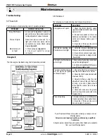
Страница 32: ...switch typicallylocatedbelowthevalvecover and turn ON 2 Ensure main power is ON or new batteries are installed in the remote control and backup battery pack if available 3 Check the 3 15A fuse in the control box and replace if necessary Pilot Igniter sparking but Pilot burner will not light 1 Verify the Inlet and Manifold Gas Pressure are within acceptable limits 2 Check all connections to gas val...

Страница 33: ...roflame Transmitter RGC3063 Replacement Screen RSCH38PFC1 RSCH38PFC2 RSCH38PFC3 RDTH38PF03 RDTH38PF02 RDTH38PF01 1 8 DWG NO WE H Finish MATERIAL DIMENSIONS ARE IN INCHES TOLERANCES FRACTIONAL 1 32 TWO PLACE DECIMAL 015 THREE PLACE DECIMAL 005 ALL BENDS ARE ASSUMED TO BE 90 UNLESS NOTED OTHERWISE Revision Date Drawn by DATE NAME THE INFORMATION CONTAINED IN THIS DRAWING IS THE SOLE PROPERTY OF CANA...

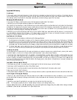
Страница 34: ... appliance 100 000 BTU H 30 KW 12 inches 12 inches M clearance to forced air supply inlet 6 feet 3 feet above air inlet N clearance above paved sidewalk or paved driveway located on public property 7 feet 7 feet P clearance under veranda porch deck or balcony 22 inches to combustibles 16 inches to non combustibles 22 inches to combustibles 16 inches to non combustibles Q clearance above roof 2 fee...

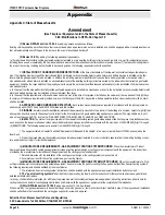
Страница 35: ...e Companies 2 The Montigo Gas Appliance must be subjected to normal use The Gas Appliances are designed to burn gas only Burning conventional fireplace fuels such as wood coal or any other solid fuel will cause damage to the Gas Appliance will produce excessive temperatures and will result in a fire hazard Limitations On Liability It is expressly agreed and understood that The Companies sole oblig...

Страница 36: ... directly in line with the exhaust vent terminal for the horizontally vented gas fueled heating appliance or equipment The sign shall read in print size no less than one half 1 2 inch in size GAS VENT DIRECTLY BELOW KEEP CLEAR OF ALL OBSTRUCTIONS 4 INSPECTION The state or local gas inspector of the side wall horizontally vented gas fueled equipment shall not approve the installation unless upon in...

Страница 37: ...Page 37 XG0816 150204 1 H 38DF PFC Peninsula Gas Fireplace Notes Notes ...

Страница 38: ...XG0816 150204 1 H38DF PFC Peninsula Gas Fireplace ...

Отзывы: