background image

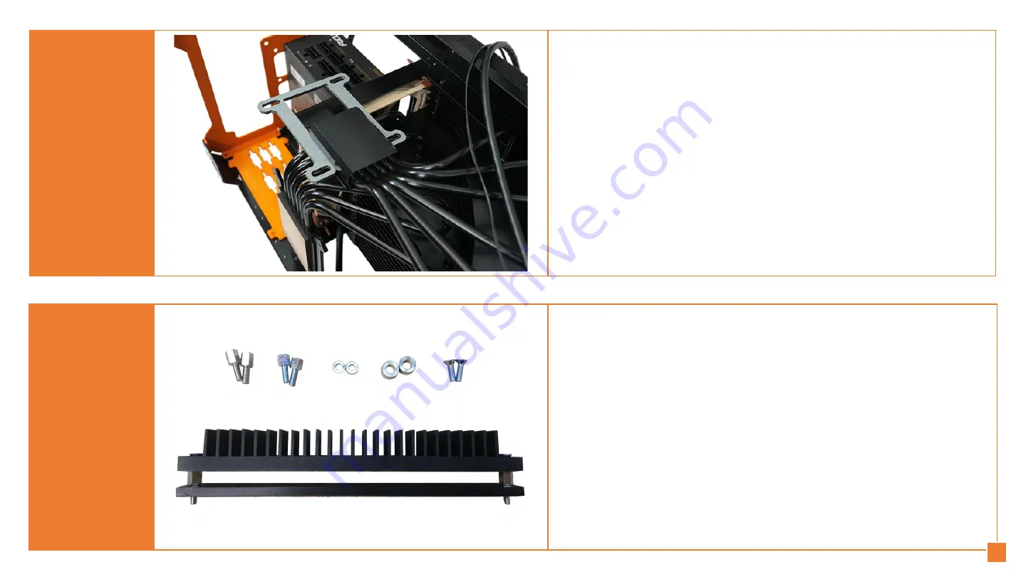
The VRM cooling should be mounted as 

shown. Depending on the thickness of 

components, spacers might be required.

STEP 27b

STEP 27

Place your First horizontally, GPU cooler

face up. Place the fixture for your graphic

card on the GPU cooler block. For some

PCBs, the fixture might be mounted from

the right to the left.

14

Содержание 364215376135191

Страница 1: ...USER MANUAL THE FIRST V1 1 2020 August ...

Страница 2: ...Prepare your tools Screwdriver wrench and cutter Take off the top skin and the top mesh Reserve the power button Unscrew the 3 aesthetic skins screws are at the back of the case STEP 1 STEP 2 1 ...

Страница 3: ...Take off the 3 aesthetic skins Unscrew the back skin and remove the skin STEP 4 STEP 3 2 ...

Страница 4: ...nd remove accessible foams Remove the adhesive taps on the metal stud between GPU cooler and CPU cooler Reserve if you want to place it back The adhesive taps are used to prevent scratches during transport Unscrew the 5 screws on the metal stud STEP 6 STEP 5 3 ...

Страница 5: ...Remove the 2 screws that fix the metal stud onto the heatsink wrench is required The First should look like this without the metal stud STEP 8 STEP 7 4 ...

Страница 6: ...If you have a box of accessories into your case remove it STEP 10 STEP 9 Remove carefully the foams that protect the CPU cooler and GPU cooler 5 ...

Страница 7: ... the fan slot 4 screws STEP 12 STEP 11 If you plan to mount a fan into your case prepare your fan with the dedicated fixtures provided in the bag HDD Fan Power Only possible with a SFX power supply Only possible with a SFX power supply 6 ...

Страница 8: ...Screw the slot fan into the case Cut the fan silicon fixtures if needed STEP 14 STEP 13 Fix the fan into the slot fan Only possible with a SFX power supply Only possible with a SFX power supply 7 ...

Страница 9: ... you mount a SFX power supply simply screw it on the dedicated part at the back of the case Screws are provided in the bag screws STEP 16 STEP 15 Start the mounting of your power supply Do not prewired 8 ...

Страница 10: ...y first remove the compatible plate for SFX power supply Then mount the power supply with screws provided in the bag screws Prewired your HDD and mount it with the screws provided in the bag screws and anti vibration kit provided in the bag HDD Fan Power 9 ...

Страница 11: ...ws provided in the bag screws Place your First horizontally CPU cooler face up If you plan to change your standard back panel with a 3D printed back panel customized start to unscrew the back panel already mounted on The First Non contractual photo 10 ...

Страница 12: ... with something between the card and the table Pay attention that most of the graphic cards loose their warranty when disassembling their cooler More information can be read on warranty policy of each brand online STEP 22 STEP 21 Remove carefully the blue plastic film used to protect the GPU and the CPU cooler blocks 11 ...

Страница 13: ...Port panel might need to be removed If necessary remove it STEP 24 STEP 23 Pay attention to the cable that connect the fan s to the PCB Unplugged carefully 12 ...

Страница 14: ...d with your case an email has been sent after you placed your order to know the components you will mount into your First this to provide you with the right fixtures STEP 26 STEP 25 Clean up the chip of your graphic card with dedicated alchohol cleaner such as Isopropyl 13 ...

Страница 15: ... the thickness of components spacers might be required STEP 27b STEP 27 Place your First horizontally GPU cooler face up Place the fixture for your graphic card on the GPU cooler block For some PCBs the fixture might be mounted from the right to the left 14 ...

Страница 16: ...lace the VRMs cooling solution on the components and use the screws provided to fix it STEP 27d STEP 27c Place the thermal pad provided at the back of the PCB where are the components you want to cool 15 ...

Страница 17: ...outing checked on step 26 with alcohol cleaner and stick the plastic washers Washers have double face adhesive STEP 28 STEP 27e You can use two VRMs cooling solution when possible as also small heatsinks provided as a kit for your memories Small heatsinks can also be used to cool VRMs when the solution is not compatible 16 ...

Страница 18: ... more space between the graphic card PCIe port and the mortherboard PCIe slot Pipes are flexible and easy to bend without risks to breake them when done carefully STEP 30 STEP 29 Mount the counternuts previously cleaned up with alcohol cleaner into the holes they should stick to the washer 17 ...

Страница 19: ...o check the position of the card chip fixture and cooler block Protect the back of the PCB with a fabric or foam Use the bag GPU and mount the columns place the spacers place the springs and place the bars Do not tight yet You can also note the position of screws and cooler block on the fixture to help you during the final assembly 18 ...

Страница 20: ...Mount your DIMs STEP 34 STEP 33 Place your processor carefully 19 ...

Страница 21: ...e thermal pad and NVMe cooling if you bought one STEP 36 STEP 35 Mount your M 2 storage if you plan to get one Non contractual photo riser isn t mounted yet Non contractual photo riser isn t mounted yet 20 ...

Страница 22: ...unted on the cooler block Use spacers and screw the columns Place your First CPU cooler face up AMD Prepare the CPU cooler block with dedicated screws provided in the bag CPU Mount the AMD fixture onto the Intel fixture already in place Only use columns AMD fixture replaces the spacers and screw the two plates with dedicated screws provided into the bag with AMD fixture 21 ...

Страница 23: ...al assembly no thermal grease Do not hesitate to put some pressure to complete the assembly of the 4 columns into holes If you do not use a riser the two cards must be pluged together via their PCIe port slot Aligned if needed by loosen the screws 22 ...

Страница 24: ...mponents touche the pipes such as NVMe or heatsinks on the mortheboard If yes remove them and use the NVMe slot at the back of the card and use smallers heatsinks available on our eshop If you use a riser for your configuration take it As you can see it can be bended easily and is very resistant Make the right shape you will need for your assembly 23 ...

Страница 25: ...l need to mount your riser for your final assembly Remove the cards then Prepare your graphic card Connect power cables and apply thermal grease For full lenght PCBs you will need to remove columns and fixture to correctly mount your graphic card onto the cooler block 24 ...

Страница 26: ...ace the metalic washers place the springs and slightly screw the bars Do not tight yet If ordered mount the VRM cooling or heatsinks provided in our kit of heatsinks and cover VRM and or memories Do not forget to clean up VRMs and memories with alchohol cleaner first 25 ...

Страница 27: ...STEP 48 STEP 47 If you use a riser mount it on your graphic card Check the chip is well covered Keep in mind the chip might not be perfectly centered only matters is to correctly covered it 26 ...

Страница 28: ...e heatsink of The First and put your motherboard on it This will be easier to wired all cables Put thermal grease on the processor Prepare your motherboard Prewired with all required cables Do not forget SSD HDD cables and do not forget the front panel cables already in place on The First 27 ...

Страница 29: ...s and screw the bars Do not tight yet Mount your mortherboard as proceeded during the trial assembly Place all cables coming from the motherboard behind the CPU cooler block power switch SATA cables USB front panel cable 24 pin power supply and sometimes audio cable Do not hesitate to put pressure onto the motherboard to make the right contact between the processor and the cooler block 28 ...

Страница 30: ...STEP 54 STEP 53 Check your cards are correctly mounted and tight the 8 bars Your motherboard should look like this 29 ...

Страница 31: ... cables pluged onto the back panel Place your First vertically upside down Mount all extended cables you ordered or already got Plug them into your motherboard and screw them onto the back panel Screws are provided in a dedicated bag with your cables 30 ...

Страница 32: ...STEP 58 STEP 57 Place your First vertically You can now start to reassemble the metal stud removed at the beginning Place your First horizontally Mount your SSDs if you have some 31 ...

Страница 33: ...STEP 58c STEP 58b Remove the ports If you have a Top Fan bracket place your 200mm fan into the bracket and screw it with screws provided with your fan Spare screws are available in your kit 32 ...

Страница 34: ...e STEP 58d If you have a Top Fan bracket with front panel screw the ports as assembled on the top of the structure If you have a Top Fan bracket with a smooth top go directly to 58g Remove the top structure 33 ...

Страница 35: ...58g STEP 58f If you have a Top Fan bracket with a smooth top remove the back panel and place the new one with self drilling screws provided Place the mesh and the top The Top Fan bracket is now assembled 34 ...

Страница 36: ...STEP 58i STEP 58h This is the back panel when assembled Upgrade your ports with new spacers privided and screw them onto the back panel 35 ...

Страница 37: ...racket is now assembled 36 Connect all cables to your power supply Do some cable management to optimize the airflow into your First Plug the fan cable if wanted but still acccessible then Position of the connector can be seen in your motherboard s user manual ...

Страница 38: ...STEP 60 Place the three aesthetic skins back skin top skin and top mesh The assembly is complete 37 ...

Отзывы: