background image

Startline S 424-S 421-S 521-S 524 

Manual Operador 

399

E

Содержание Startline S 421

Страница 1: ...Startline S 524 S 521 S 421 S 424 Code 4 135704 08 2018 Manuale d uso Operator s manual Manuel d utilisation Betriebsanleitung Manual de uso CE info mondolfoferro it www mondolfoferro it...

Страница 2: ...rezzatura sia sempre in condizioni ottimali di esercizio Nel caso in cui si osservino eventuali malfunzionamenti o probabili situazioni di pericolo arrestare immedia tamente la macchina e porre rimedi...

Страница 3: ...canale rovescio Bloccaggio interno esterno con griffe in acciaio Stallonatura Ruote standard Ruote ribassate Smontaggio Ruote standard con protezioni in plastica per torretta e leva Corretto posiziona...

Страница 4: ...___ _____________________________________________________________________ _____________________________________________________________________ ________________________________________________________...

Страница 5: ...AGGIO 25 5 SOLLEVAMENTO MOVIMENTAZIONE 27 5 1 SPAZIO DI INSTALLAZIONE 28 6 DESCRIZIONE MACCHINA 29 6 1 POSIZIONE DELL OPERATORE 30 7 DIMENSIONI D INGOMBRO MM 30 8 PRINCIPALI ELEMENTI DI FUNZIONAMENTO...

Страница 6: ...ICI 58 10 2 C PARTI FUNZIONALI 59 10 2 D POSIZIONAMENTO ADESIVI 59 10 2 E SMONTAGGIO MONTAGGIO PNEUMATICO 60 10 3 HSA 21 61 10 3 A INSTALLAZIONE 61 10 3 B DATI TECNICI 61 10 3 C PARTI FUNZIONALI 61 10...

Страница 7: ...e la manutenzione Il corsivo utilizzato per fare riferimento a parti specifiche del presente manuale che offrono infor mazioni aggiuntive o chiarimenti Tali riferimenti devono essere letti per ottene...

Страница 8: ...IONE 1 Incasodiesecuzionenoncorrettadelleproceduredimanutenzionefornitenelpresente manuale o di mancata osservanza delle altre istruzioni in esso contenute potrebbero verificarsi incidenti All interno...

Страница 9: ...sicurezza e non eviter l esplosione di pneumatici e cerchi Mantenere gli astanti a distanza PERICOLO 7 Pericolo di schiacciamento Presenza di parti mobili Il contatto con parti in movimento pu provoca...

Страница 10: ...i poco per volta controllando nel frattempo la pressione lo pneu matico il cerchio e il tallone NON superare mai i limiti di pressione indicati dal fabbricante 15 Questa attrezzatura presenta parti in...

Страница 11: ...per inutilizzo o per manutenzione della macchina o dell impianto pneumatico dell officina pu lasciareinpressionegliattuatoripneumatici Sca ricare l impianto pneumatico della macchina agendo sui comand...

Страница 12: ...O AUTO CENTRANTE 11 446435 ADESIVO PERICOLO TOR RETTA 12 446434 ADESIVO PERICOLO D URTO PALO POSTERIORE NON SO STARE DIETRO LA MACCHINA 13A 461931 ADESIVO PERICOLO DI GON FIAGGIO 13B 462778 ADESIVO PE...

Страница 13: ...XXXXX XX XX XXXXXXXXX QUAL SYS CERTIFIED ANNO DI COSTRUZIONE MANUFACTURED Mod V A kW Hz Ph bar psi ADESIVO MATRICOLA MO DELLO 24 463509 ADESIVO RIBALTAMENTO COLONNA 439213 ADESIVO APERTURA CHIU SURA A...

Страница 14: ...e S 424 S 421 S 521 S 524 Manuale Operatore 1 2 3 4 5 6 7 9 10 11 12 13A 14 16 17 21 22 23 24 25 26 25 12 11 10 Startline S 524 Startline S 521 12 12 25 25 5 6 23 1 3 24 2 4 7 21 9 16 17 26 11 11 10 1...

Страница 15: ...Startline S 424 S 421 S 521 S 524 Manuale Operatore 15 I 13B 13C Startline S 421 Startline S 424 2 24 2 7 21 4 1 3 3 13A 10 10 26 17 17 16 11 9 22 21 4 7 1 24 9 16 26 5 6 23 10 11 13B 10 14 27 5 6 23...

Страница 16: ...Pericolo di schiacciamento stallonatore parte n 446442 Pericolo recipiente sotto pressione parte n 425211A Pericolo di scossa elettrica parte n 461931 Pericolo di gonfiaggio parte n 462778 Pericolo di...

Страница 17: ...Terminale di collegamento a terra parte n 462081A Pericolo schiacciamento mani 450005 POSTER AVVERT DI SICUREZZA Deve essere applicato vicino allo smonta gomme in posizione visibile all operatore 1 2...

Страница 18: ...stiche Assicurarsi che la pressione disponibile e le prestazioni dell impianto ad aria compressa siano compatibili con quelle necessarie al corretto funzionamento della macchina vedere la sezione Dati...

Страница 19: ...28 esterno da12 a26 Alimentazione elettrica monofase 115 230 10 Volt 50 60Hz trifase 230 400 10 Volt 50 60Hz DV 230 10 Volt 1ph 50 60Hz LarghezzacerchioStartlineS421 StartlineS424 da4 a13 Larghezzacer...

Страница 20: ...a in modo affidabile per stabilire se siano ne cessarie o meno ulteriori precauzioni I fattori che determinano il livello di esposizione a cui soggetto l operatore comprendono la durata dell esposizio...

Страница 21: ...esta macchina deve essere utilizzata esclusivamente per smontare e montare pneumatici per autoveicoli da sui cerchi utilizzando gli utensili dei quali dotata Qualsiasi altro utiliz zo da ritenersi imp...

Страница 22: ...ndizioni ed efficienti e che all interno della macchina o nelle sue vicinanze non vi siano corpi estranei o detriti stracci attrezzi ecc che potrebbero pregiudicarne il funzionamento Questi controlli...

Страница 23: ...ballo larghezza 910 mm profondit 1150 mm altezza 1000 mm Peso con imballo Versione standard 250 kg Versione TI 260 kg Condizioni dell ambiente di trasporto e stoccaggio macchina Temperatura 25 55 C Pe...

Страница 24: ...cchina dal pallet assicurarsi che dallo stesso siano stati rimossi gli elementi mostrati qui di seguito ATTENZIONE Liberarelamacchinadalla parte superiore dell im ballo accertarsi che non abbia subito...

Страница 25: ...arlo con l anello seeger M fig 5A CollegareiltuboG Fig 5D alraccordointerme dio collegato al rubinetto alzapalo H Startline S 521 Registrare la posizione da entrambi i lati della colonna Il gioco tra...

Страница 26: ...Registrazione ribaltamento Fig 5M la velocit del ribaltamento palo deve essere regolata non superiore a 0 71 rad s Dopo molti cicli di ribaltamento nel tem po potrebbe essere necessario una nuova tara...

Страница 27: ...palo A fig 6D Montare la valvola di sicurezza B Fig 6D Connettere il tubo G alla valvola Fig 6E Rimontare cofano laterale N Fig 6A 5 SOLLEVAMENTO MOVIMENTAZIONE Per la rimozione della macchina dal pal...

Страница 28: ...DI INCENDIO Non utilizzare la macchina in aree nelle qualipotrebbeessereespostaavaporiinfiammabili benzina solventipervernici etc Non installare la macchina in una zona angusta o posizionarla al di s...

Страница 29: ...in posizione verticale per la stallonatura e orizzontale per il montaggio e lo smontaggio Gli azionamenti sono eseguiti dall operatore mediante pedaliera Ogni macchina fornita di una targhetta Fig 9...

Страница 30: ...iere la macchina dal pallet assicurarsi che dallo stesso siano stati rimossi gli elementi mostrati qui di seguito ATTENZIONE RISCHIO DI LESIONI DA SCHIACCIAMENTO Il ribaltamento della colonna e l aper...

Страница 31: ...ollareaccuratamenteilcorrettofunzionamentodiciascuncomandodellamacchina Per evitare incidenti e lesioni l apparecchiatura dev essere installata adeguatamente azionata in modo corretto e sottoposta a p...

Страница 32: ...enso antiorario 11 Paletta stallonatrice paletta mobile per staccare il tallone dal cerchio 12 Gruppo filtro Regolatore Lubrificatore gruppo che permette di regolare filtrare deumidificare e lubrifica...

Страница 33: ...e S 424 S 421 S 521 S 524 Manuale Operatore 33 I 2 1 19 3 5 6 14 8 4 7 9 10 11 13 12 18 22 8 1 2 3 16 17 15 20 17 21 14 22 1 2 3 24 12 23 25 26 5 6 10 9 11 13 3 17 21 27 Startline S 521 S 524 Startlin...

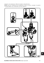
Страница 34: ...0 9 11 13 3 17 27 28 16 15 PERICOLO DI ESPLOSIONE Per le caratteristiche tecniche avvertimenti manutenzione e qualsiasi altra informazione relativa al serbatoio dell aria opzionale il manuale d uso e...

Страница 35: ...I URTO Il ribaltamento del braccio operante pu creare un potenziale pericolo di urto con parti del corpo L operazione di ribaltamento deve essere eseguita nella posizione B ATTENZIONE ATTENZIONE 12a 1...

Страница 36: ...larghezza maggiore B e la lar ghezzami noreC Lopneumaticodeveesseremontato osmontatoconlaruotaposizionatasull autocentrante econillatodellalarghezzaminoreCrivoltoversol alto RUOTE SPECIALI Ruote con c...

Страница 37: ...ONE Premere il pedale A Fig 14B Startline S 521 S 524 Fig 14A Startline S 424 S 421 e portarlo in configurazione completamente ab bassato In questa configurazione le griffe sono completamente chiuse S...

Страница 38: ...Fig 15A Startline S 524 Per ruote estremamente larghe oltre 350 mm posizionare il fermo B come mostrato in figura 15B Posizionare la ruota come indicato in fig 16 e avvicinare la paletta dello stallon...

Страница 39: ...re danni ai talloni fig 17 9 4 BLOCCAGGIO RUOTA Durante la movimentazione dei cunei di bloccaggio ruota tenere le mani e altre parti del corpo lontano dalle parti in movimento della macchina ATTENZION...

Страница 40: ...mere il pedale D per aprire completamente le griffe dell autocentrante Fig 18D A macchina completamente ferma e scollegata dalla rete svitare grano bloccaggio A Fig 18E e vite fissaggio griffa B Fig 1...

Страница 41: ...o ruote Il settaggio dei diametri 11 24 o 13 27 per mezzo del dispositivo di regola zione vaeffettuatoadautocentrantecompletamentefermosenzaagiresuicomandi ATTENZIONE Startline S 424 S 524 11 24 13 26...

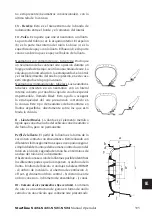
Страница 42: ...pertura delle griffe a uomo presente e quindi fermarle nella posizione desiderata Se si blocca il cerchio dall esterno Fig 19b pre posizionare i cunei di bloccaggio aiutandosi con i riferimentideidiam...

Страница 43: ...24 Startline S 521 Premere il pedale per riportare la colonna in posizione di lavoro Fig 21 Tirare il pulsante posizione Z per sbloccare contemporaneamente il braccio verticale e quello orizzontale fi...

Страница 44: ...a creare la distanza di circa 2 mm tra torretta e cerchio B Fig 23A Bloccare il braccio verticale agendo sulla leva A Fig 24 9 5 c SMONTAGGIO RUOTA Inserire e posizionare la leva alzatalloni sulla tor...

Страница 45: ...l pedale d azionamento Per la rotazione in senso opposto sar suffi ciente sollevare il pedale Sollevare il secondo tallone manualmente sulla testina poi ruotare il piatto autocen trante in senso orari...

Страница 46: ...ti o arrugginiti e che essi non abbiano bavature affilate sui fori della valvola Verificare che lo pneumatico sia in buone condizioni e non vi siano segni di danni PERICOLO Prima d iniziare le operazi...

Страница 47: ...ICI UHP APPROVATI E RUN FLAT Per una descrizione dettagliata della procedura di montaggio smontaggio degli pneu matici UHP e RUN FLAT si prega di fare riferimento alle istruzioni nel manuale elaborato...

Страница 48: ...gonfi possono esplodere provocando la dispersione in aria di detriti che possono causare incidenti 2 Pneumatici e cerchi che non hanno lo stesso diametro sono detti non corrispondenti Non tentare di m...

Страница 49: ...ata all interno del cerchio o se il cerchio o lo pneumatico sono difettosi o danneggiati Non oltrepassare mai la pressione raccomandata dal fabbricante dello pneumatico Lo smontagomme non un dispositi...

Страница 50: ...i descritte sotto assicurarsi che non sia presente sporcizia polveri o altre impurit in prossimit degli ugelli di gonfiaggio Si consiglia l uso di occhiali protettivi ATTENZIONE Verificarecheentrambii...

Страница 51: ...odiametro adesempio pneumaticoda16pollicie1 2conuncerchioda16pollici ATTENZIONE Premere a fondo per un breve intervallo il pedale di gonfiaggio fig 36 Il pneumatico si espande e porta i talloni in pos...

Страница 52: ...soltanto dapersonalequalificatoedautorizzatodalcostruttore L installazionedapartedipersonale NON qualificato comporta la perdita delle garanzie sulle prestazioni del dispositivo L accessorio pu essere...

Страница 53: ...collegareiltubodelregolatoresmontagomme collegare il raccordo a Y e tubo 8 in dotazione collegandolo con il regolatore del Helper Connettere il raccordo Y con regolatore smon tagomme fig 42 6 Solo Hel...

Страница 54: ...m 270 mm Corsa braccio 350 mm 350 mm 10 1 d Parti funzionali 1 Palo verticale 2 Supporto scorrevole 3 Piede appoggio regolabile 4 Premitallone 5 Comando helper 6 Braccio pneumatico pressore 7 Utensile...

Страница 55: ...oggiare la ruota sul piatto autocentrante precedentemente stallonata posizionare il braccio con cono in corrispon denza foro centrale cerchio fig 46 azionare la valvola in modo da premere la ruota sul...

Страница 56: ...allone inferiore e il cerchio fig 51 premere il pedale di rotazione e sollevare Lo smontaggio del secondo tallone si pu effettuare nel modo tradizionale con la leva oppure utilizzando il rullo premita...

Страница 57: ...liberare la ruota dal rullo e dal premitallone 10 2 HSU 24 10 2 a Installazione Installare la base fissa 1 fig 54 sulla parte superiore del palo installare il finecorsa 2 come mostrato in fig 54 Inst...

Страница 58: ...olacomandosullatodelbraccio principale con n 4 viti M6x10 fig 59 Installareilsupportoaccessorinelretrodello Smontagomme n 2 viti M8x25 fig 60 Regolareilcentraggiocomefig 61 installareil conoecentraloc...

Страница 59: ...Manopola bloccaggio G Rullo pressore H Fissaggio accessori I Cono corto J Cono lungo K Disco alzatallone L Perno bloccaggio F Rullo pressore N Braccio pressore O Perno sblocco rotazione P Valvola cont...

Страница 60: ...so il basso Bloccare il complesso agendo sul pedale dell auto centrante fig 66 Sbloccare il braccio dal complesso agendo sul comando e rimuovere il cono Bloccarelarotazionedeibraccinellaposizionedesid...

Страница 61: ...oppio con rondella e dado Fig 72 Fissare il braccio pressore nella parte superiore tramite rondella e dado Fig 73 Collegare il tubo aria alimentazione 10 3 b Dati tecnici HSA21 Forza cilindro pneumati...

Страница 62: ...ne S 424 S 421 S 521 S 524 Manuale Operatore 1 2 3 10 3 d Posizionamento adesivi Rif Codice Descrizione 1 Targhetta comando sbloccag gio 2 4 405458 Adesivo ingombro 3 462081 Adesivo pericolo di schiac...

Страница 63: ...Startline S 424 S 421 S 521 S 524 Manuale Operatore 63 I 10 3 e Smontaggio Montaggio pneumatico Smontaggio A B C...

Страница 64: ...64 Startline S 424 S 421 S 521 S 524 Manuale Operatore Montaggio...

Страница 65: ...le connessioni del cavo nella spina Il motore non gira Controllare i microinterruttori della pedaliera solo per motoinverter Controllare il comando rotazione motore della pedaliera Sostituire la sche...

Страница 66: ...aggio la torretta utensile non si solleva o si alza troppo dal cerchio Piastrina bloccaggio non registrata Registrare piastrina Durante il ribaltamento del palo i bracci orizzontale e verticale scivol...

Страница 67: ...0 Manometro difettoso o danneggiato Sostituire il manometro Il lubrificatore non lubrifica Manca olio nel lubrificatore Rabboccare con olio SAE20 non detergente nel lubrificatore Lubrificatore rotto S...

Страница 68: ...stratta e ruotandola al termine della regolazione riportare la manopola nella posizione di bloccaggio spingendola verso il basso fig 42a La regolazione della portata del lubrificante si ottiene ruotan...

Страница 69: ...Startline S 424 S 421 S 521 S 524 Manuale Operatore 69 I NOTA per le indicazioni d avvertenza sull olio fare riferimento all apposito capitolo riportato nel manuale d uso della macchina a b c e d 42...

Страница 70: ...arare preventivamente i particolari elettrici elettronici plastici e ferrosi Procedere quindi alla rottamazione diversificata come previsto dalle norme vigenti 14 INFORMAZIONI AMBIENTALI Laseguentepro...

Страница 71: ...ti favorevoli all ambiente riciclare l imballo interno ed esterno con cui il prodotto fornito e smaltire in modo adeguato le batterie usate solo se contenute nel prodotto Con il vostro aiuto si pu rid...

Страница 72: ...rti concentrazioni di vapori o nebbie trasportare il colpito all aria aperta e in seguito al presidio medico Occhi irrigare abbondantemente con acqua e rivolgersi al pi presto al presidio medico Pelle...

Страница 73: ...o per fornire una buona resistenza all abrasione e una buona aderenza in condi zioni di asciutto e bagnato cos come delle condizioni di funzionamento silenziose 2 Bordo o rinforzo un inserto di tessut...

Страница 74: ...o che indica la circonferenza della parte superiore del tallone ed utilizzato come riferimento per controllare il corretto centraggio dello pneumatico sul cerchio dopo il montaggio 7 Cordolo di protez...

Страница 75: ...le strato di gomma speciale impermeabile chiamato liner Questo contribuisce ad assicurare la tenuta dell aria in pressione contenuta nella carcassa Questo tipo di pneumatici deve essere montato su cer...

Страница 76: ...beless Sistema di gonfiaggio che facilita il gonfiaggio dei pneumatici tubeless Intallonatura Operazione che si ottiene nella fase di gonfiaggioegarantisceunperfettocentraggiotratallone e bordo cerchi...

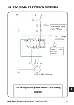
Страница 77: ...Startline S 424 S 421 S 521 S 524 Manuale Operatore 77 I 18 SCHEMA ELETTRICO GENERALE...

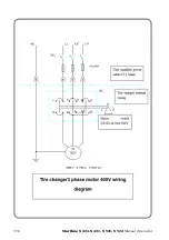
Страница 78: ...78 Startline S 424 S 421 S 521 S 524 Manuale Operatore...

Страница 79: ...Startline S 424 S 421 S 521 S 524 Manuale Operatore 79 I...

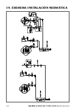
Страница 80: ...80 Startline S 424 S 421 S 521 S 524 Manuale Operatore 19 SCHEMA IMPIANTO PNEUMATICO 70 20X262 70 20X262 186 20X150 70 20X310 70 20X310 186 20X150...

Страница 81: ...Startline S 424 S 421 S 521 S 524 Manuale Operatore 81 I Note...

Страница 82: ...t is in excellent working order In case any malfunction or possible dangerous situation are observed immediately shut down the machine and resolve the situation before you proceed For any question rel...

Страница 83: ...sed channel rims Internal external locking with steel jaws Bead breaking Standard wheels Low profile wheels Demounting Standard wheels with plastic guards for tool head and lever Proper tool head posi...

Страница 84: ..._____________________________________________________________________ _____________________________________________________________________ ___________________________________________________________...

Страница 85: ...DLING 103 3 UNWRAPPING 104 4 MOUNTING 105 5 LIFTING HANDLING 107 5 1 INSTALLATION AREA 108 6 DESCRIPTION OF THE MACHINE 109 6 1 OPERATOR POSITION 110 7 OVERALL DIMENSIONS mm 110 8 MAIN WORKING ELEMENT...

Страница 86: ...TALLATION 137 10 2 B TECHNICAL DATA 138 10 2 C FUNCTIONAL PARTS 139 10 2 D LABELS PLACEMENT 139 10 2 E TYRE MOUNTING DEMOUNTING 140 10 3 HSA 21 141 10 3 A INSTALLATION 141 10 3 B TECHNICAL DATA 141 10...

Страница 87: ...procedures and maintenance Italics are used to refer to specific parts of this manual that offer additional information or clarifications These references must be read in order to obtain information a...

Страница 88: ...ce WARNING 1 Accidents could occur if the maintenance procedures described in this manual are not executed correctly or if the other instructions it contains are not observed This manual makes continu...

Страница 89: ...rom exploding Keep all persons not working on the machine out of the working area DANGER 7 Risk of crushing Presence of moving parts Contact with moving parts can cause acci dents The machine can only...

Страница 90: ...the bead NEVER exceed the pressure limits indicated by the manufacturer 15 The internal parts in this equipment could create contacts or sparks if exposed to flammable vapours petrol paint thinners so...

Страница 91: ...essure Discharge the machine pneumatic system using the controls on the actuators 24 Use a lifting device if the wheel weighs more than 10 kg with a lifting frequency of more than 20 wheels hour 1 2 b...

Страница 92: ...ANGER TOOLHEAD 12 446434 LABEL RISK OF INJURY REAR POLE DONOTSTANDBEHIND THE MACHINE 13A 461931 LABEL DANGER OF INFLA TION 13B 462778 LABEL DANGER OF INFLA TION ONLY AMERICAN MAR KET 13C 432740 LABEL...

Страница 93: ...SYS CERTIFIED ANNO DI COSTRUZIONE MANUFACTURED Mod V A kW Hz Ph bar psi LABEL MODEL SERIAL NUM BER 24 463509 LABEL COLUMN TILTING 439213 LABEL TURNTABLE OPEN ING CLOSING 439212 LABEL BEAD BREAKER AC T...

Страница 94: ...ne S 424 S 421 S 521 S 524 Operator manual 1 2 3 4 5 6 7 9 10 11 12 13A 14 16 17 21 22 23 24 25 26 25 12 11 10 Startline S 524 Startline S 521 12 12 25 25 5 6 23 1 3 24 2 4 7 21 9 16 17 26 11 11 10 13...

Страница 95: ...Startline S 424 S 421 S 521 S 524 Operator manual 95 UK 13B 13C Startline S 421 Startline S 424 2 24 2 7 21 4 1 3 3 13A 10 10 26 17 17 16 11 9 22 21 4 7 1 24 9 16 26 5 6 23 10 11 13B 10 14 27 5 6 23...

Страница 96: ...part n 446431 Risk of bead breaker crushing part n 446442 Danger pressurised container part n 425211A Danger of electric shock part n 461931 Inflation hazard part n 462778 Inflation hazard for North...

Страница 97: ...62081A Risk of crushing hands 450005 WARNING POSTER OF SAFETY It must be applied close to the tyre changer in a position visible to the operator 1 2 c ELECTRICAL AND PNEUMATIC CONNECTIONS A good earth...

Страница 98: ...le pressure and performance of the compressed air system are compatible with what is necessary for correct machine operation see the section Technical data For the correct operation of the machine the...

Страница 99: ...phase 115 230 10 Volt 50 60Hz three phase 230 400 10 Volt 50 60Hz DV 230 10 Volt 1ph 50 60Hz Rim width Startline S 421 Startline S 424 from 4 to 13 Rim width Startline S 521 from 4 to 14 Rim width St...

Страница 100: ...xposure levels are connected this relationcannotbeusedasasafeparametertodeterminewhetherornotfurtherprecautions are necessary The noise level to which the operator is exposed to depends on a number of...

Страница 101: ...unt vehicle tyres from on the rims using the provided tools Any other use is improper and may result in injury 1 5 PERSONNEL TRAINING 1 Employers are responsible for providing a training program for a...

Страница 102: ...e checks must be carried out Before starting the machine At regular time intervals After any modification or repair The machine may only be started after this pre use check is successfully completed D...

Страница 103: ...ht with package Standard version 250 kg TI version 260 kg Ambient conditions for machine transport and storage Temperature 25 55 C Do not stack other goods on top of the packing to avoid damaging it W...

Страница 104: ...removing the machine from the pallet make sure the items shown below have been removed WARNING Remove the upper part of the package and make sure that the machine has not suffered damage during transp...

Страница 105: ...th Circlip M Fig 5A Connect pipe G Fig 5D to the intermediate union connected to the pole lifting tap H Startline S 521 Adjust the position from both sides of the column The clearance between the scre...

Страница 106: ...the pole Fig 5L Tilting adjustment Fig 5M the speed of the pole tiltingmustbeadjustednothigherthan0 71rad s After many tilting cycles over time it may be necessary to re calibrate Adjust valves A on...

Страница 107: ...nstall the inflation pressure gauge box on the pole A Fig 6D Fit the safety valve B Fig 6D Connect pipe G to the valve Fig 6E Refit the side cover N Fig 6A 5 LIFTING HANDLING In order to remove the ma...

Страница 108: ...EXPLOSION OR FIRE Do not use the machine in areas that could be ex posed to inflammable vapours petrol paint solvents etc Do not install the machine in a narrow area or position it below floor level D...

Страница 109: ...idly constructed It operates with the wheel in a vertical position for bead breaking and in a horizontal position for mounting and demounting tyres All machine movements are controlled by the operator...

Страница 110: ...ting C Inflation area 9a 9b Before removing the machine from the pallet make sure the items shown below have been removed WARNING RISKOFINJURYDUETOCRUSHING Thecolumntiltingandtheself centringclamp ope...

Страница 111: ...on and layout of all controls Carefully check that all controls on the machine are working properly To avoid accidents and injury the machine must be installed properly operated correctly and serviced...

Страница 112: ...kwise Lifted Unstable position anticlockwise rotation 11 Bead breaker shoe movable shoe to detach the bead from the rim 12 Filter Regulator Lubricator Unit regulates pressure filters removes water and...

Страница 113: ...e S 424 S 421 S 521 S 524 Operator manual 113 UK 2 1 19 3 5 6 14 8 4 7 9 10 11 13 12 18 22 8 1 2 3 16 17 15 20 17 21 14 22 1 2 3 24 12 23 25 26 5 6 10 9 11 13 3 17 21 27 Startline S 521 S 524 Startlin...

Страница 114: ...9 11 13 3 17 27 28 16 15 RISK OF EXPLOSION With regard to the technical characteristics warnings maintenance and any other information about the air tank optional consult the relevant operator s and...

Страница 115: ...ilting of the operating arm can create a potential risk of impact with parts of the body The tilting operation must be performed in position B WARNING WARNING 12a 12b AVOID ANY PHYSICAL DAMAGE Before...

Страница 116: ...sition of channel A on the rims IdentifythegreaterwidthBandthesmallerwidth C The tyre must be mounted and demounted with the wheel on the turntable with the smallest width side C facing upwards SPECIA...

Страница 117: ...moving parts WARNING Press pedal A Fig 14B Startline S 521 S 524 Fig 14A Startline S 424 S 421 and bring it into completely lowered configuration In this configuration the jaws are completely closed...

Страница 118: ...the tyre Fig 15A Startline S 524 For extremely wide wheels over 350 mm position the stop B as shown in figure 15B Position the wheel as shown in fig 16 and move the bead breaker shoe near the rim edg...

Страница 119: ...tate demounting and avoid damaging the beads fig 17 9 4 CLAMPING THE WHEEL Keep your hands and other body parts away from moving parts of the machine while moving the wheel locking wedges WARNING If t...

Страница 120: ...al D to fully open the turntable jaws Fig 18D With the machine completely stopped and disconnected from the mains unscrew the locking nut A Fig 18E and jaw fixing screw B Fig 18F Adjust the position a...

Страница 121: ...heels Setting the diameter range 11 24 or 13 27 using the adjustment device must becarriedoutwiththeturntablecompletelystoppedwithoutactingonthecommands WARNING Turntable jaws opening and closing is c...

Страница 122: ...it is possible to carry out dead man control of jaws opening and then stop them in the desired position If the rim is blocked from the outside Fig 19b pre position the locking wedges using the refere...

Страница 123: ...demounting 9 5 a TOOL HEAD POSITIONING Startline S 524 Startline S 521 Pressthepedal tomovethecolumn into the working position Fig 21 Pull the Z position button to release the verticalandhorizontalarm...

Страница 124: ...ontal arm using the handwheel B Fig 24A to create the distance of about 2 mm between the tool head and the rim B Fig 23A Lock the vertical arm using the lever A Fig 24 9 5 c WHEEL DEMOUNTING Insert an...

Страница 125: ...tionoftheturntablecanbestopped at any time by releasing the pedal To rotate in the opposite direction simply raise up the pedal Lift the second bead manually on the head then rotate the turntable cloc...

Страница 126: ...r rusted and that they have no sharp burrs on the valve holes Check that the tyre is in good condition with no signs of damage DANGER Before you start with tyre mounting operations lubricate the beads...

Страница 127: ...accessory supplied on request 9 7 APPROVED UHP AND RUN FLAT TYRE DEMOUNTING AND MOUNTING PROCEDURE ForadetaileddescriptionoftheUHPandRUNFLATtyredemounting mountingprocedure please refer to the instruc...

Страница 128: ...ed tyres can explode producing hazardous flying debris that may result in an accident 2 Tyres and rims that do not have the same diameter are mismatched Never attempt to mount or inflate any tyre and...

Страница 129: ...rinted inside the rim or if the rim or the tyre is defective or damaged Never exceed the pressure recommended by the tyre manufacturer The tyre changer is not a safety device and does not prevent tyre...

Страница 130: ...king wedges Before starting with the operations described below make sure there is no dirt dust orotherimpuritiesneartheinflationnozzles Itisadvisabletowearprotectivegoggles WARNING Verify that both u...

Страница 131: ...do not have the same diameter e g 16 and 1 2 inch tyre and a 16 inch rim WARNING Fully press the inflation pedal for a short time Fig 36 The tyre will expand and the beads will seat To improve the ope...

Страница 132: ...be carried out by qualified personnel authorized by the manufacturer Installation by NON qualified personnel does not ensure the product correct performance The accessory can only be installed on MOND...

Страница 133: ...ngerregulatorhose con nect the Y connector and the hose 8 supplied by connecting it with the Helper regulator Connect the Y connector with the tyre changer regulator Fig 42 6 Helper HTB24 only Complet...

Страница 134: ...roller min radius 270 mm 270 mm Arm stroke 350 mm 350 mm 10 1 d Functional parts 1 Vertical pole 2 Sliding support 3 Adjustable support foot 4 Bead presser 5 Helper control 6 Pneumatic pressure arm 7...

Страница 135: ...e place the arm with cone in the rim central hole Fig 46 activate the valve so as to press the wheel on the plate Fig 47 then clampthewheelwiththeappropriatepedal When working on reversed channel rims...

Страница 136: ...roller Position the presser roller tangent to the ex ternal diameter of the rim Fig 51 Fitting the tyres Place the tyre on the rim and tilt the pole forward then fit the first bead fig 52 Placethetop...

Страница 137: ...washer on the fixed base fig 55 Install arm 1 Fig 56 on the fixed base 2 and tightenwiththescrewandwasherpreviously unscrewed Remove the rotation shaft by releasing the retainer 2 with a wrench Fig 5...

Страница 138: ...g as in fig 61 install the coneandcentreitwiththeturntableandlock the screw 1 fig 62 Then fasten the 4 screws of the fixed base 2 fig 62 and tighten nut 3 Install the Y connection fig 63 10 2 b Techni...

Страница 139: ...ng presser arm F Clamping handle G Presser roller H Accessories fastening I Short cone J Long cone K Bead lift disc L Locking pin F Presser roller N Presser arm O Rotation release pin P Control valve...

Страница 140: ...ol downwards Lock the assembly by acting on the pedal of the turntable fig 66 Unlock the arm from the assembly by acting on the control and remove the cone Lock the rotation of the arms in the desired...

Страница 141: ...Install the new double pin with washer and nut Fig 72 Installthepresserarmintheupperpartwithwasher and nut Fig 73 Connect air supply hose 10 3 b Technical data HSA21 Pneumatic cylinder force at 8 bar...

Страница 142: ...142 Startline S 424 S 421 S 521 S 524 Operator manual 1 2 3 10 3 d Labels placement Ref Code Description 1 Unlocking control plate 2 4 405458 Label dimensions 3 462081 Label risk of crushing...

Страница 143: ...Startline S 424 S 421 S 521 S 524 Operator manual 143 UK 10 3 e Tyre mounting demounting Demounting A B C...

Страница 144: ...144 Startline S 424 S 421 S 521 S 524 Operator manual Mounting...

Страница 145: ...ck cable connections in the plug The motor is not running Check the microswitches of the pedal unit only for motor inverter Check the motor rotation control of the pedal unit Replace the inverter boar...

Страница 146: ...er Cylinder seals worn Replace the seals Replace the bead breaker cylinder After clamping the tool head does not rise or rises too far from rim Clamping plate not adjusted Adjust the plate When the po...

Страница 147: ...eedle fails to return to 0 Pressure gauge faulty or damaged Replace the pressure gauge The lubricator does not work No oil in lubricator Top up lubricator with SAE20 non detergent oil Lubricator broke...

Страница 148: ...d by pulling the handle to the extracted position and turning it At the end of the adjustment return the handle to the locked position pushing it downwards fig 42a The lubricant flow rate adjustment i...

Страница 149: ...Startline S 424 S 421 S 521 S 524 Operator manual 149 UK NOTE for oil warnings refer to the specific chapter in the machine user manual a b c e d 42...

Страница 150: ...local regulations 14 ENVIRONMENTAL INFORMATION The disposal procedure described below only applies to equipment with the barred bin symbol on the rating plate This product may contain substances that...

Страница 151: ...the amount of natural resources used to produce electrical and electronic equipment minimise the use of landfills to dispose of old products and improve quality of life by preventing the discharge of...

Страница 152: ...affected person to the open air and seek medical attention immediately Eyes rinse with plenty of running water and seek medical attention immediately Skin wash with soap and water 16 FIREFIGHTING EQU...

Страница 153: ...wet conditions as well as quiet operating conditions 2 Edge or bracing It is an insert of metallic or textile fabric placed at the outer part of the bead it is used to protect the carcass plies from s...

Страница 154: ...mounting 7 Protectiveband Thisisacircumferentialmarking in the area of the sidewall which is more exposed to accidental rubbing 8 Sidewall This is the area between the shoulder and the centring band I...

Страница 155: ...xed but non permanent basis Rim profile The rim profile is the shape of the section in contact with the tyre It is made with different geometric shapes that serve to ensure easy assembly of the tyre i...

Страница 156: ...rfectcentringbetweenthe bead and the rim edge Bead pressing tool A tool intended for use when mounting the top bead It is positioned so that it engages the shoulder of the rim and maintains the upper...

Страница 157: ...Startline S 424 S 421 S 521 S 524 Operator manual 157 UK 18 GENERAL WIRING DIAGRAM...

Страница 158: ...158 Startline S 424 S 421 S 521 S 524 Operator manual...

Страница 159: ...Startline S 424 S 421 S 521 S 524 Operator manual 159 UK...

Страница 160: ...160 Startline S 424 S 421 S 521 S 524 Operator manual 19 PNEUMATIC SYSTEM DIAGRAM 70 20X262 70 20X262 186 20X150 70 20X310 70 20X310 186 20X150...

Страница 161: ...Startline S 424 S 421 S 521 S 524 Operator manual 161 UK Notes...

Страница 162: ...res de travail en toute s curit S assurer que l quipement est toujours en parfait tat de marche En cas de dysfonctionnements ou de situations probables de danger arr ter imm diatement l quipement et p...

Страница 163: ...Jantes creux renvers Blocage interne externe avec griffes en acier D talonnage Roues standard Roues surbaiss es D montage Roues standard avec protections en plastique pour t te op rante et levier Posi...

Страница 164: ...___ _____________________________________________________________________ _____________________________________________________________________ ________________________________________________________...

Страница 165: ...ANUTENTION 183 3 D BALLAGE 184 4 MONTAGE 185 5 LEVAGE MANIEMENT 187 5 1 SURFACE D INSTALLATION 188 6 DESCRIPTION MACHINE 189 6 1 POSITION DE L OP RATEUR 190 7 DIMENSIONS D ENCOMBREMENT MM 190 8 L MENT...

Страница 166: ...CES FONCTIONNELLES 219 10 2 D POSITIONNEMENT DES AUTOCOLLANTS 219 10 2 E D MONTAGE MONTAGE PNEUMATIQUE 220 10 3 HSA 21 221 10 3 A INSTALLATION 221 10 3 B DONN ES TECHNIQUES 221 10 3 C PI CES FONCTION...

Страница 167: ...pement les proc dures et l entretien L italique est utilis pour se r f rer des partiessp cifiquesdupr sentmanuel quifournissentdesinformationscompl mentaires ou des claircissements Ces r f rences doiv...

Страница 168: ...avec la machine en lieu s r pour toute consultation future ATTENTION 1 Une mauvaise ex cution des proc dures d entretien fournies dans le pr sent manuel oul inobservationdesautresinstructionspourraitp...

Страница 169: ...de pneus et de jantes Veiller ce que les personnes restent distance de s curit DANGER 7 Danger d crasement Pr sence de pi ces mobiles Le contact avec des organes et des pi ces en mouvement peut provoq...

Страница 170: ...r lant entre temps la pression le pneu la janteetletalon NEjamaisd passerleslimitesdepressionprescritesparlefabricant 15 Cet quipementpr sentedespartiesetpi cesinternes lesquellesencasd exposition des...

Страница 171: ...d entretien de la machine ou du circuit pneumatique de l atelier les actionneurs pneumatiques peuvent rester sous pression D charger le circuit pneumatique de la machine en agissant sur les commandes...

Страница 172: ...11 446435 AUTOCOLLANT DANGER T TE OP RANTE 12 446434 AUTOCOLLANT DANGER DE COLLISION DU POTEAU ARRI RE NEPASSTATIONNER DERRI RE LA MACHINE 13A 461931 AUTOCOLLANT DANGER DE GONFLAGE 13B 462778 AUTOCOLL...

Страница 173: ...XX XXXXXXXXX QUAL SYS CERTIFIED ANNO DI COSTRUZIONE MANUFACTURED Mod V A kW Hz Ph bar psi AUTOCOLLANT NUM RO DE S RIE MOD LE 24 463509 AUTOCOLLANT BASCULEMENT COLONNE 439213 AUTOCOLLANT OUVERTURE FER...

Страница 174: ...ine S 424 S 421 S 521 S 524 Manuel Op rateur 1 2 3 4 5 6 7 9 10 11 12 13A 14 16 17 21 22 23 24 25 26 25 12 11 10 Startline S 524 Startline 321 12 12 25 25 5 6 23 1 3 24 2 4 7 21 9 16 17 26 11 11 10 13...

Страница 175: ...Startline S 424 S 421 321 S 524 Manuel Op rateur 175 F 13B 13C Startline S 421 Startline S 424 2 24 2 7 21 4 1 3 3 13A 10 10 26 17 17 16 11 9 22 21 4 7 1 24 9 16 26 5 6 23 10 11 13B 10 14 27 5 6 23...

Страница 176: ...n 446431 Danger d crasement d talonneur partie n 446442 Danger d un r servoir sous pression partie n 425211A Danger d lectrocution partie n 461931 Danger de gonflage partie n 462778 Danger de gonflag...

Страница 177: ...mise la terre partie n 462081A Risque d crasement des mains 450005 POSTER AVERT DE S CURIT Il doit tre appliqu pr s du d monte pneu dans une position visible par l op rateur 1 2 c RACCORDEMENT LECTRIQ...

Страница 178: ...pas admis S assurerquelapressiondisponibleetlesperformancesdel installation aircomprim soient compatiblesaveccellesn cessairespourlefonctionnementcorrectdelamachine ser f rer la section Donn es techni...

Страница 179: ...has e 115 230 10 Volt 50 60Hz triphas e 230 400 10 Volt 50 60Hz DV 230 10 Volt 1ph 50 60Hz Largeur de la jante Startline S 421 Startline S 424 de 4 13 Largeur de la jante Startline 321 de 4 14 Largeur...

Страница 180: ...ission et ceux d exposition il n a pas une valence fiable dans la d finition de la n cessit de pr cautions suppl mentaires prendre Les facteurs d terminant le niveau d exposition auquell op rateurests...

Страница 181: ...e exclusivement utilis e pour d monter remplacer et remonter les pneus pour v hicules automobiles de sur jantes l aide des outils dont elle est dot e Toute autre utilisation est jug e impropre et peut...

Страница 182: ...ifier l absence de corps trangers ou de d tritus chiffons outils etc l int rieur de la machine ou proximit susceptibles d en compromettre le bon fonctionnement Ces contr les doivent tre effectu s Avan...

Страница 183: ...largeur 910 mm longueur 1150 mm hauteur 1000 mm Poids avec emballage Version standard 250 kg Version TI 260 kg Conditions du milieu de transport et stockage de la machine Temp rature 25 55 C Pour vit...

Страница 184: ...vant de retirer la machine de la palette s assurer que les l ments suivants ont t retir s de la palette ATTENTION Lib rer la machine de la partie sup rieure de l emballage s assurer qu elle n a pas t...

Страница 185: ...poteau et le fixer avec l anneau M fig 5A Raccorder le tuyau G Fig 5D au raccord interm diaire raccord au robinet du montant H Startline 321 Noter la position des deux c t s de la colonne Lejeuentrel...

Страница 186: ...sculement Fig 5M La vitesse de basculement du poteau doit tre r gl e 0 71 rad s au maximum Apr splusieurscyclesdebasculementdans letemps unnouvel talonnagepeuts av rern cessaire R gler les soupapes A...

Страница 187: ...ur le poteau A Fig 6D Monter la soupape de s curit B Fig 6D Raccorder le tuyau G la vanne Fig 6E Remonter le capot lat ral N Fig 6A 5 LEVAGE MANIEMENT Pour la d pose de la machine de la palette utilis...

Страница 188: ...et abrit s DANGER D EXPLOSION OU D INCENDIE Ne pas utiliser la machine dans des zones o elle pourrait tre expos e aux vapeurs inflammables essence solvants pour peinture etc Ne pas installer la machi...

Страница 189: ...la roue en position verticale pour le d talonnage et en position horizontale pour le montage et le d montage Les entra nements sont effectu s par l op rateur au moyen d une p dale Chaque machine est q...

Страница 190: ...gonflage 9a 9b Avant de retirer la machine de la palette s assurer que les l ments suivants ont t retir s de la palette ATTENTION RISQUE DE L SIONS DUES L CRASEMENT Le basculement de la colonne et l...

Страница 191: ...ontr leravecattentionlefonctionnementcorrectdechaquecommandedelamachine Pour viter des accidents et des pr judices corporels l appareil doit tre install de fa on ad quate man uvr correctement et soumi...

Страница 192: ...ans le sens inverse des aiguilles d une montre 11 Palette de d talonnage palette mobile pour le d talonnage du talon de la jante 12 Groupe filtre R gulateur Lubrificateur groupe de r gulation filtrati...

Страница 193: ...ine S 424 S 421 321 S 524 Manuel Op rateur 193 F 2 1 19 3 5 6 14 8 4 7 9 10 11 13 12 18 22 8 1 2 3 16 17 15 20 17 21 14 22 1 2 3 24 12 23 25 26 5 6 10 9 11 13 3 17 21 27 Startline 321 S 524 Startline...

Страница 194: ...11 13 3 17 27 28 16 15 DANGER D EXPLOSION Pour les caract ristiques techniques les avertissements l entretien l entretien et toute autre information relative au r servoir d air en option le manuel d u...

Страница 195: ...ION Le basculement du bras de commande permet de cr erundangerpotentieldecollisionavecdesparties du corps L op ration de basculement doit tre effectu e en position B ATTENTION ATTENTION 12a 12b V I T...

Страница 196: ...e B et la largeur la plus petite C Le pneumatique doit tre mont ou d mont avec la roue sur l autocentreur et le c t de la largeur la plus troite C vers le haut ROUES SP CIALES Roues avec jantes en all...

Страница 197: ...Appuyer sur la p dale A Fig 14B Startline 321 S 524 Fig 14A Startline S 424 S 421 etl amener laconfigurationcompl tement abaiss e Dans cette configuration les griffes sont compl tement ferm es D gonf...

Страница 198: ...ig 15A Startline S 524 Pour les roues extr mement larges plus de 350 mm positionner la but e B comme indiqu sur la figure 15B Positionner la roue d apr s la fig 16 et rapprocher la palette du d talonn...

Страница 199: ...e d montage et viter d endommager les talons fig 17 9 4 BLOCAGE ROUE Tenir les mains et les autres parties du corps loign es des pi ces mobiles de la machine lors du maniement de coins ATTENTION En ca...

Страница 200: ...daleD pourouvrircompl tementlesgriffesdel autocentreur Fig 18D Lorsque la machine est compl tement arr t e et d connect e du r seau d visser la vis sans t te de blocage A Fig 18E et la vis de fixatio...

Страница 201: ...vant de d monter les roues Lesdiam tres 11 24 ou13 27 doivent trer gl s l aidedudispositifder glage lorsquel autocentreurest l arr tcompletetquelescommandesnesontpasactionn es ATTENTION Startline S 42...

Страница 202: ...ilestpossibledecontr ler l ouverture des griffes la pr sence de l op rateur et ensuite les bloquer dans la position souhait e Si vous bloquez la jante de l ext rieur Fig 19b pr positionner les coins d...

Страница 203: ...GE DE LA ROUE 9 5 a POSITIONNEMENT DE LA T TE OP RANTE Startline S 524 Startline 321 Appuyersurlap dale pourramener la colonne en position de travail Fig 21 TirerleboutondepositionZ pourd bloquer les...

Страница 204: ...verture du bras horizontal l aide de la manivelle B Fig 24A jusqu ce qu une distanced environ2mmsoitcr eentrelat te op rante et la jante B Fig 23A Bloquer le bras vertical l aide du levier A Fig 24 9...

Страница 205: ...nt en rel chant la p dale d entra nement Pour tourner dans le sens inverse il suffit de soulever la p dale Souleverledeuxi metalon lamainau dessus delat te puistournerleplateauautocentreur dans le sen...

Страница 206: ...ont pas de bavures pointues sur les trous des soupapes V rifier que le pneu est en bon tat et qu il n y a aucun signe d endommagement DANGER Avantdecommencerlesop rationsdemontage lubrifier les talon...

Страница 207: ...ONTAGE ET MONTAGE DES PNEUS UHP APPROUV S ET RUN FLAT Pourunedescriptiond taill edelaproc duredemontage d montagedespneusUHPet RUNFLAT veuillezvousr f rerauxinstructionsdumanuelpr par parWDK Associati...

Страница 208: ...1 Des pneus trop gonfl s peuvent clater et provoquer la dispersion de d tritus susceptibles de causer des accidents 2 Des pneus et des jantes qui n ont pas le m me diam tre sont incompatibles et donc...

Страница 209: ...e imprim e l int rieur de la jante ou si la jante ou le pneu sont d fectueux ou endommag s Ne jamais d passer la pression prescrite par le fabricant du pneu Le d monte pneus n est pas un dispositif de...

Страница 210: ...ns la suite s assurer qu il n y a pas de salet de poussi re ou d autres impuret s proximit des buses de gonflage Des lunettes de protection sont recommand es ATTENTION V rifier que les deux talons sup...

Страница 211: ...jante de diam tre diff rent exemple pneu de 16 5 sur jante de 16 ATTENTION Appuyer a fond sur la p dale de gonflage Fig 36 Le pneu se dilate et place les talons dans une position stable Pour un meill...

Страница 212: ...que par du personnel qualifi et autoris par le fabricant Installation par le personnel NON qualifi entra nera la perte des garanties de performance de l appareil L accessoire ne doit tre install que...

Страница 213: ...rancher le tuyau du dispositif de r glage du d monte pneus raccorder le connecteur en Y et le tuyau 8 fourni en le connectant au r gulateurHelper RaccorderleconnecteurenY avecledispositifder glagedud...

Страница 214: ...mm Course du bras 350 mm 350 mm 10 1 d Pi ces fonctionnelles 1 Poteau vertical 2 Support coulissant 3 Pied d appui r glable 4 Presse talon 5 Commande Helper 6 Bras pneumatique du presseur 7 Outil 8 O...

Страница 215: ...teau autocentreur positionner le bras avec le c ne en correspondance avec le trou traversant de la jante fig 46 actionner la valve de mani re presser la roue sur le plateau fig 47 ensuitebloquerlaroue...

Страница 216: ...de rotation et la soulever vers le haut Le d montage du deuxi me talon peut se faire de mani re traditionnelle avec le levier ou en utilisant le rouleau presse talon Positionner le rouleau tangent au...

Страница 217: ...t du presse talon 10 2 HSU 24 10 2 a Installation Installer la base fixe 1 fig 54 sur le haut du poteau installer l interrupteur de fin de course 2 d apr s la fig 54 Installer les 4 vis M12x40 et les...

Страница 218: ...sur le c t du brasprincipal l aidede4visM6x10 fig 59 Installer le support d accessoires l arri re dud monte pneus l aideden 2visM8x25 fig 60 R gler le centrage d apr s la fig 61 installer lec neetlec...

Страница 219: ...locage G Rouleaux presseur H Fixation des accessoires I C ne court J C ne long K Disque dispositif l ve talon L Goupille de blocage F Rouleau presseur N Bras presseur O Goupille de d blocage rotation...

Страница 220: ...in vers le bas Bloquerl ensemble l aidedelap daledel autocentreur fig 66 D bloquer le bras de l ensemble l aide de la commande et retirer le c ne Verrouillerlarotationdesbrasdanslapositionsouhait e fi...

Страница 221: ...double avec la rondelle et l crou Fig 72 Fixerlebraspresseurenhaut l aided unerondelle et d un crou Fig 73 Raccorder le tuyau d alimentation en air 10 3 b Donn es techniques HSA21 Force v rin pneumat...

Страница 222: ...S 424 S 421 S 521 S 524 Manuel Op rateur 1 2 3 10 3 d Positionnement des autocollants R f Code Description 1 Plaque commande de d blocage 2 4 405458 Autocollant encombrement 3 462081 Autocollant dange...

Страница 223: ...Startline S 424 S 421 321 S 524 Manuel Op rateur 223 F 10 3 e D montage montage pneumatique D montage A B C...

Страница 224: ...224 Startline S 424 S 421 S 521 S 524 Manuel Op rateur Montage...

Страница 225: ...ns du c ble dans la fiche Le moteur ne tourne pas Contr ler les microrupteurs du p dalier uniquement pour inverseurs Contr ler la commande de rotation moteur du p dalier Remplacer la carte de l invers...

Страница 226: ...oints Remplacer le v rin d talonneur Suite au blocage la t te op rante outil ne se l ve pas ou se l ve de mani re excessive de la jante Plaque de blocage pas r gl e R gler la plaque Pendant le bascule...

Страница 227: ...tredelecturepressiondespneusnerevientpas 0 Manom tre d fectueux ou ab m Remplacer le manom tre Le lubrificateur ne fonctionne pas Huile insuffisante dans le lubrificateur Faire l appoint avec de l hu...

Страница 228: ...ifi en tirant la poign e dans la position extraite et en la tournant la fin du r glage le bouton revient en position bloqu e en la poussant vers le bas fig 42a Led bitdelubrifiantestr gl entournantlav...

Страница 229: ...Manuel Op rateur 229 F Nettoyer avec un chiffon sec viter tout contact avec des solvants REMARQUE pour les indications d avertissement sur l huile se r f rer au chapitre appropri du manuel d utilisat...

Страница 230: ...RMATIONS CONCERNANT LA D MOLITION En cas de d molition de la machine s parer pr alablement les composants lectriques lectroniques plastiques et ferreux Proc der donc la mise la casse s lective comme p...

Страница 231: ...s o le produit est mis au rebut Nousvousrecommandons enoutre d adopterd autresmesuresdeprotectiondel environnement recycler les emballages int rieur et ext rieur dans lesquels le produit est livr limi...

Страница 232: ...ations lev es de vapeurs ou brouillards d placer la personne bless e l air libre et ensuite la conduire au poste m dical Yeux laver abondamment l eau et se contacter d s que possible le poste m dical...

Страница 233: ...sistance l abrasion et une bonne adh rence dans des conditions s ches et humides ainsi que des conditions de fonctionnement silencieux 2 Bord ou renfort Il s agit d un insert en m tal ou en tissu tex...

Страница 234: ...inte 6 Borddecentrage Ils agitd unepetitemarqueindiquant lacirconf rencedelapartiesup rieuredutalonetservant de r f rence pour v rifier le centrage correct du pneu sur la jante apr s montage 7 Cordon...

Страница 235: ...constitu s d un pneu dont le flanc int rieur est recouvert d une fine couche de caoutchouc sp cial imperm able l eau appel rev tement Ceci permet d assurer l tanch it de l air sous pression contenu d...

Страница 236: ...interne b et le dos c rev tement externe Syst medegonflagedestubeless Syst medegonflage qui facilite le gonflage des pneus tubeless Entalonnage Cette op ration est obtenue pendant la phase de gonflag...

Страница 237: ...Startline S 424 S 421 321 S 524 Manuel Op rateur 237 F 18 SCH MA LECTRIQUE G N RAL...

Страница 238: ...238 Startline S 424 S 421 S 521 S 524 Manuel Op rateur...

Страница 239: ...Startline S 424 S 421 321 S 524 Manuel Op rateur 239 F...

Страница 240: ...240 Startline S 424 S 421 S 521 S 524 Manuel Op rateur 19 SCH MA CIRCUIT PNEUMATIQUE 70 20X262 70 20X262 186 20X150 70 20X310 70 20X310 186 20X150...

Страница 241: ...Startline S 424 S 421 321 S 524 Manuel Op rateur 241 F Notes...

Страница 242: ...enden Arbeiten Sicherstellen dass sich das Ger t stets in optimalem Betriebszustand befindet Sollten eventuelle Betriebsst rungen oder m gliche Gefahrensituationen beobachtet werden die Maschine das G...

Страница 243: ...en mit umgekehrtem Bett Innen Au enverriegelung mit Stahlklauen Abdr cken Standardreifen Niederquerschnittsreifen Demontage Standardreifen mit Kunststoffschutz f r Montagekopf und Hebel Korrekte Posit...

Страница 244: ...____ _____________________________________________________________________ _____________________________________________________________________ _______________________________________________________...

Страница 245: ...UNG UND HANDLING 263 3 AUSPACKEN 264 4 MONTAGE 265 5 HEBEN INTERNER TRANSPORT 267 5 1 F R MONTAGE ERFORDERLICHER PLATZ 268 6 BESCHREIBUNG DER MASCHINE 269 6 1 POSITION DES BEDIENERS 270 7 ABMESSUNGEN...

Страница 246: ...a Montage 297 10 2 b Technische Daten 298 10 2 c Funktionsteile 299 10 2 d Positionierung der Aufkleber 299 10 2 e Demontage Montage des Reifens 300 10 3 hSA 21 301 10 3 a Montage 301 10 3 b Technisc...

Страница 247: ...Teile des vorliegenden Handbuchs die zus tzliche Informationen oder Erkl rungen enthalten wurde die Kursivschrift verwendet Es besteht die Pflicht diese Bezugshinweise zu lesen um zus tzliche Informa...

Страница 248: ...ht korrekten Ausf hrung der im vorliegenden Handbuch angef hrten Wartungsverfahren oder mangelnden Befolgung anderer darin enthaltenen Anweisungen k nnteeszuUnf llenkommen ImvorliegendenHandbuchwirdst...

Страница 249: ...icht verhindern dass Reifen und Felgen explodieren k nnen Andere Personen fernhalten GEFAHR 7 Quetschungsgefahr Vorhandensein beweglicher Teile Der Kontakt mit Teilen die sich bewegen kann Unf lle ver...

Страница 250: ...rittweiseaufpumpenundzwischendurchdenDruck denReifenselbst die Felge und den Wulst berpr fen NIEMAILS die vom Hersteller angegebenen Druckgrenzwerte berschreiten 15 DiesesGer tverf gt berinnereTeile d...

Страница 251: ...Wartung der Maschine oder der pneumatischen Anlage der Werkstatt k nnen die pneumatischen Antriebe weiterhin unter Druck stehen Die pneumatische Anlage derMaschinedurchBet tigenderSteuerungderAntrieb...

Страница 252: ...NNFUTTER 11 446435 AUFKLEBER GEFAHR DURCH MONTAGEKOPF 12 446434 AUFKLEBER ANSTOSSGEFAHR AN HINTERER S ULE SICH NICHTHINTERDERMASCHINE AUFHALTEN 13A 461931 AUFKLEBER GEFAHR DURCH AUFBLASVORGANG 13B 462...

Страница 253: ...XXXXXX QUAL SYS CERTIFIED ANNO DI COSTRUZIONE MANUFACTURED Mod V A kW Hz Ph bar psi AUFKLEBER SERIENNUMMER DES MODELLS 24 463509 AUFKLEBER S ULENKIPPUNG 439213 AUFKLEBER FFNUNG SCHLIESSUNG SELBSTZENTR...

Страница 254: ...S 424 S 421 S 521 S 524 Bedienungsanleitung 1 2 3 4 5 6 7 9 10 11 12 13A 14 16 17 21 22 23 24 25 26 25 12 11 10 Startline S 524 Startline S 521 12 12 25 25 5 6 23 1 3 24 2 4 7 21 9 16 17 26 11 11 10...

Страница 255: ...tartline S 424 S 421 S 521 S 524 Bedienungsanleitung 255 D 13B 13C Startline S 421 Startline S 424 2 24 2 7 21 4 1 3 3 13A 10 10 26 17 17 16 11 9 22 21 4 7 1 24 9 16 26 5 6 23 10 11 13B 10 14 27 5 6 2...

Страница 256: ...446431 Quetschgefahr Abdr cker Teil Nr 446442 Gefahr unter Druck stehender Beh lter Teil Nr 425211A Stromschlaggefahr Teil Nr 461931 Gefahr durch Aufblasen Teil Nr 462778 Gefahr durch Aufblasen f r n...

Страница 257: ...s Teil Nr 462081A Quetschgefahr f r H nde 450005 POSTER SICHERHEITS WARNUNGEN Muss in der N he der Reifenmontiermaschine in einer f r den Bediener sichtbaren Position angebracht werden 1 2 c ELEKTRISC...

Страница 258: ...gbare Druck und die Leistung des Druckluftsystems mit denen kompatibel sind die f r den ordnungsgem en Betrieb des Ger ts erforderlich sind siehe den Abschnitt Technische Daten F r den ordnungsgem en...

Страница 259: ...tern von 14 b bis 28 extern von 12 bis 26 Stromversorgung einphasig 115 230 10 Volt 50 60 Hz dreiphasig 230 400 10 Volt 50 60 Hz DV 230 10 Volt 1ph 50 60 Hz Felgenbreite Startline S 421 Startline S 42...

Страница 260: ...t k nnendiesenichtzuverl ssigverwendetwerden umfestzustellen obweitereVorkehrungenerforderlichsindodernicht ZudenFaktoren diedieExpositionswerte denenderBedienerausgesetztist bestimmen geh rendieExpos...

Страница 261: ...fen von aufFelgenf rFahrzeugeundMotorr derunterAnwendungdermitgeliefertenWerkzeuge verwendet werden Jeder andere Einsatz ist als unsachgem zu betrachten und kann Unf lle verursachen 1 5 SCHULUNG DES P...

Страница 262: ...n deren N he keine Fremdk rper Lappen Ger tschaften usw oder Teilchen befinden einen Inspektionsgang um die Maschine herum machen Auszuf hren sind diese Kontrollen Vor Inbetriebsetzung der Maschine In...

Страница 263: ...ebenen Position gehalten werden Abmessungen der Verpackung Breite 910 mm Tiefe 1150 mm H he 1000 mm Gewicht mit Verpackung Standardversion 250 kg Version TI 260 kg Transport und Lagerraumbedingungen d...

Страница 264: ...Bevor Sie die Maschine von der Palette nehmen sicherstellen dass die nachstehend dargestellten Teile von der Palette entfernt wurden ACHTUNG DieMaschinevomoberen Teil der Verpackung befreien sicherste...

Страница 265: ...emSeeger RingM Abb 5A Schlie en Sie den Schlauch G Abb 5D an Zwischenanschlussan deramdenS ulenhubhahn H Startline S 521 angeschlossen ist Stellen Sie die Position auf beiden Seiten der S ule ein Das...

Страница 266: ...meters an der S ule Abb 5L Neigungseinstellung Abb 5M dieKippgeschwindigkeit der S ule darf nicht ber 0 71 rad s eingestellt werden NachvielenKippzyklenkann berdieZeithinwegeine erneute Kalibrierung e...

Страница 267: ...der S ule A Abb 6D Montieren Sie das Sicherheitsventil B Abb 6D Schlie enSiedenSchlauchGandasVentil Abb 6E Montieren Sie nun die seitliche Haube N wieder Abb 6A 5 HEBEN INTERNER TRANSPORT Zur Entfern...

Страница 268: ...ipiert EXPLOSIONS ODER BRANDGEFAHR Die Maschine nicht in Bereichen in denen sie brennbarenD mpfenausgesetztseink nnte Benzin Farbl sungsmittelusw verwenden DieMaschinenichtineinemengenBereichoderunter...

Страница 269: ...wichten Die in einer soliden Bauweise gebaute Maschine h lt das Rad in einer vertikalen Position f r das Abdr cken und in einer horizontalen Position f r die Montage und Demontage Die Antriebe werden...

Страница 270: ...Maschine von der Palette nehmen sicherstellen dass die nachstehend dargestellten Teile von der Palette entfernt wurden ACHTUNG VERLETZUNGSGEFAHR DURCH QUETSCHUNG Das Kippen der S ule und das ffnen Sch...

Страница 271: ...nzelnen Ger testeuerungen sorgf ltig berpr fen Zum Schutz vor Unf llen und Verletzungen muss die Ausr stung zweckgerecht installiert in korrekter Weise betrieben und der regelm igen Wartung unterzogen...

Страница 272: ...Drehung im Uhrzeigersinn Gehoben instabile Position gegen den Uhrzeigersinn 11 Abdr ckschaufel bewegliche Schaufel zum L sen der Wulst von der Felge 12 Filtergruppe Regler Schmierstoffgeber Gruppe zu...

Страница 273: ...S 424 S 421 S 521 S 524 Bedienungsanleitung 273 D 2 1 19 3 5 6 14 8 4 7 9 10 11 13 12 18 22 8 1 2 3 16 17 15 20 17 21 14 22 1 2 3 24 12 23 25 26 5 6 10 9 11 13 3 17 21 27 Startline S 521 S 524 Startl...

Страница 274: ...25 26 5 6 10 9 11 13 3 17 27 28 16 15 EXPLOSIONSGEFAHR Bez glich der technischen Eigenschaften den Warnhinweisen der Wartung und allen anderen Informationen zum Luftbeh lter optional das Benutzer und...

Страница 275: ...rch das Kippen des Arbeitsarms kann es zu einer m glichenKollisionsgefahrmitK rperteilenkommen Der Kippvorgang muss in der Position B durchgef hrt werden ACHTUNG ACHTUNG 12a 12b K R P E R L I C H E S...

Страница 276: ...ste Breite B und die schmalste Breite C Der Reifen muss mit dem Rad im selbstzentrierenden Spannfutter und der Seite der schmalsten Breite C nach oben gerichtet montiert oder demontiert werden SPEZIAL...

Страница 277: ...as Pedal A Abb 14B Startline S 521 S 524 Abb 14A Startline S 424 S 421 und bringen Sie es in die vollst ndig abgesenkteKonfiguration IndieserKonfiguration sind die Klauen vollst ndig geschlossen Den R...

Страница 278: ...Abb 15A Startline S 524 Bei extrem breiten R dern ber 350 mm den Anschlag B wie in Abbildung 15B dargestellt positionieren Positionieren Sie das Rad wie in Abb 16 gezeigt und bringen Sie die Abdr cksc...

Страница 279: ...s oberen Wulstes um die Demontage zu erleichtern und Sch den an den W lsten zu vermeiden Abb 17 9 4 EINSPANNEN DES RADS Halten Sie beim Umgang mit den Klemmkeilen die H nde und andere K rperteile von...

Страница 280: ...enSiedasPedal umdieKlauendesselbstzentrierendenSpannfutters vollst ndig zu ffnen Abb 18D Wenn die Maschine vollst ndig gestoppt und vom Netz getrennt ist l sen Sie den Sperrstift A Abb 18E und die Bef...

Страница 281: ...ren Die Durchmesser 11 24 oder 13 27 m ssen ber die Einstellvorrichtung eingestellt werden wenn das selbstzentrierende Spannfutter vollst ndig stillsteht und die Steuerbefehle nicht bet tigt werden AC...

Страница 282: ...ung der Klauen ber die Totmann Steuerung steuern und daher in der gew nschten Position stoppen WennSiedieFelgevonau eneinspannen Abb 19b die Klemmkeile mit Hilfe der Durchmesserbez ge auf dem selbstze...

Страница 283: ...21 Dr cken Sie das Pedal um die S ule wieder in die Arbeitsposition zu bringen Abb 21 Ziehen Sie die Taste der Z Position um den vertikalen und den horizontalen Arm gleichzeitig zu entriegeln Abb 22A...

Страница 284: ...Abstand von ca 2 mm zwischen dem Montagekopf und der Felge entsteht B Abb 23A Verriegeln Sie den vertikalen Arm durch bet tigen des Hebels A Abb 24 9 5 c ABNAHME DES RADS SetzenSiedenWulsthebereinund...

Страница 285: ...als gestoppt werden Zum Drehen in die entgegengesetzte Richtung einfach das Pedal anheben Heben Sie den zweiten Wulst von Hand ber den Montagekopf und drehen Sie dann den selbstzentrierenden Spanntell...

Страница 286: ...rate an den Ventilbohrungen aufweisen berpr fen Sie dass der Reifen sich in einem guten Zustand befindet und keine Anzeichen von Sch den aufweist GEFAHR Vor Beginn der Montagearbeiten die W lste schmi...

Страница 287: ...e erh ltliches Zubeh r 9 7 DEMONTAGE UND MONTAGEVERFAHREN VON ZUGELASSENEN UHP UND RUN FLAT REIFEN Eine detaillierte Beschreibung der Vorgehensweise bei der Montage Demontage von UHP und RUN FLAT Reif...

Страница 288: ...e in die Luft projektieren Teilen in der Luft f hren die Unf lle verursachen k nnen 2 Reifen und Felgen die nicht denselben Durchmesser haben werden als nicht untereinander bereinstimmend betrachtet N...

Страница 289: ...ngepr gt bereinstimmt oder die Felge bzw der Reifen defekt oder besch digt ist Den vom Reifenhersteller empfohlenen Druck nie berschreiten Die Reifenmontiermaschine ist keine Sicherheitseinrichtung un...

Страница 290: ...len dass sich an den Aufblasd sen kein Schmutz Staub oder andere Verunreinigungen befinden Das Tragen einer Schutzbrille wird empfohlen ACHTUNG berpr fen dass der obere und untere Wulst sowie der Wuls...

Страница 291: ...cht denselben Durchmesser aufweisen zum Beispiel 16 5 Reifen und 16 Felge miteinander montieren ACHTUNG Das Aufpumppedal kurz vollkommen niederdr cken Abb 36 Der Reifen dehnt sich aus und bringt die W...

Страница 292: ...eller autorisiertes Fachpersonal Die Montage durch Personal das NICHT qualifiziert ist f hrt zum Verlust der Leistungsgarantie der Vorrichtung DasZubeh rkannausschlie lichnuraufdieReifenmontiermaschin...

Страница 293: ...rauben 5 L sen Sie den Schlauch des Reglers der Reifenmontiermaschine verbinden Sie den Y Anschluss und den mitgeliefertem Schlauch 8 indem Sie ihn mit dem Regler des Helper verbinden Verbinden Sie de...

Страница 294: ...0 mm 270 mm Armhub 350 mm 350 mm 10 1 d Funktionsteile 1 Vertikale S ule 2 Verschiebbarer Halter 3 Verstellbarer St tzfu 4 Wulstdr cker 5 Bedienelement Helper 6 Pneumatischer Andr ckarm 7 Werkzeug 8 Z...

Страница 295: ...des ausrichten das vorher vom Reifen getrennte Rad auf den selbstzentrierenden Spannteller auflegen den Arm mit dem Konus am zentralen Loch der Felge positionieren Abb 46 das Ventil so bet tigen dass...

Страница 296: ...m Sitz da er weiter an der Felge anhaftet In diesen F llen die Scheibe zwischen dem unteren Wulst und der Felge einsetzen Abb 51 das Drehsteuerpedal dr cken und anheben Die Demontage des zweiten Wulst...

Страница 297: ...kzeugs befindet Den Steuerhebel f r den Anstieg bet tigen das Rad von der Walze und dem Wulstniederhalter befreien 10 2 HSU 24 10 2 a Montage Installieren die den festen Sockel 1 Abb 54 auf dem oberen...

Страница 298: ...Abb 59 seitlich am Hauptarm Montieren Sie den Zubeh rhalter mit 2 SchraubenM8x25 Abb 60 aufderR ckseite der Reifenmontiermaschine StellenSiedieZentrierunggem Abb 61ein montieren Sie den Konus und zen...

Страница 299: ...F Feststellgriff G Andr ckrolle H Zubeh rbefestigung I Kurzer Kegel J Langer Kegel K Wulstheberscheibe L Sperrbolzen F Andr ckrolle N Andr ckarm O Drehentriegelungsbolzen P Steuerventil Q Zylinder 10...

Страница 300: ...rierendenSpannfutters Abb 66 Entriegeln Sie den Arm durch Bet tigen der Steuerung von der Einheit und entfernen Sie den Konus Sperren Sie die Schwenkung der Arme in der gew nschten Position Abb 67 dr...

Страница 301: ...lbolzen mit Unterlegscheibe und Mutter Abb 72 Befestigen Sie den Andr ckarm oben mit einer Unterlegscheibe und einer Mutter Abb 73 Schlie en Sie den Luftversorgungsschlauch an 10 3 b Technische Daten...

Страница 302: ...S 424 S 421 S 521 S 524 Bedienungsanleitung 1 2 3 10 3 d Positionierung der Aufkleber Bez Artikelnummer Beschreibung 1 Schild Entriegelungssteuerung 2 4 405458 Aufkleber Abmessungen 3 462081 Aufkleber...

Страница 303: ...Startline S 424 S 421 S 521 S 524 Bedienungsanleitung 303 D 10 3 e Demontage Montage des Reifens Demontage A B C...

Страница 304: ...304 Startline S 424 S 421 S 521 S 524 Bedienungsanleitung Montage...

Страница 305: ...r Motor dreht nicht Die Mikroschalter der Pedaleinheit kontrollieren nur bei Motoinverter Die Motordrehsteuerung der Pedaleinheit kontrollieren Die Inverterplatine austauschen nur bei Motoinverter Den...

Страница 306: ...rdichtungen Dichtungen auswechseln Den Wulstabdr ckzylinder austauschen Nach dem Verriegeln hebt sich der Montagekopf nicht oder zu weit von der Felge Einspannplatte nicht eingestellt Das Pl ttchen ei...

Страница 307: ...ifens geht nicht auf 0 zur ck Defekter oder besch digter Manometer Den Manometer ersetzen Die Schmiervorrichtung schmiert nicht In der Schmiervorrichtung fehlt l Mit l SAE20 die Schmiervorrichtung nac...

Страница 308: ...ng kann durch Ziehen des Knopfes in die ausgezogene Stellung und dessen Drehen ge ndert werden Nach BeendigungderEinstellungwirddenGriffwiederindieverriegelteStellungzur ckdr cken Abb 42a Der Schmierm...

Страница 309: ...ungsanleitung 309 D Mit einem trockenen Tuch reinigen Den Kontakt mit L sungsmitteln vermeiden HINWEIS bez glich der Warnhinweise zum l ist Bezug auf das entsprechenden Kapitel in der Bedienungsanleit...

Страница 310: ...EN ZUR VERSCHROTTUNG Bei eventueller Verschrottung des Ger ts s mtliche elektrischen elektronischen sowie Kunststoff und Eisenteile vorsorglich trennen Anschlie end die getrennte Entsorgung gem den ei...

Страница 311: ...ere als die vorgeschriebene Entsorgung des Produkts ist verboten und wird nach den einschl gigen Gesetzen und Vorschriften des Landes in dem das Produkt entsorgt wird geahndet Dar ber hinaus sollten n...

Страница 312: ...n mit aufgerautem Gewebe Brille im Falle von Spritzern Sch rzen die gegen Mineral le best ndig sind Schutzschilder im Falle von Spritzer Mineral l Erste Hilfe Anweisungen Verschlucken Sich an einen Ar...

Страница 313: ...ensetzt Der Reifen muss der die Last tragen die bertragung der Motorleistung sicherstellen das Fahrzeug steuern zur Haftung auf der Stra e und zum Bremsen beitragen zur Aufh ngung des Fahrzeugs beitra...

Страница 314: ...oneinander so dass die Biegebewegungen der Seitenwand beim Abrollen nicht auf die Lauffl che bertragen werden 4 Wulstkern Es ist ein Metallring der aus mehreren Stahldr hten besteht Die Karkassenlagen...

Страница 315: ...pitze der Wulst a ist die interne Ecke Der Sporn b ist der innerste Teil des Wulstes Der Sockel c ist der Auflagebereich mit der Felge Die Aussparung d ist der konkave Teil auf das Felgenhorn aufliegt...

Страница 316: ...ssen und die Abdichtung der unter Druck stehenden Luft in einem Innenschlauch bzw bei Tubless einer Abdeckung erm glicht Sie besteht aus drei Teilen der Ventilkappe a zum Schutz des inneren Mechanismu...

Страница 317: ...Startline S 424 S 421 S 521 S 524 Bedienungsanleitung 317 D 17 ALLGEMEINGER SCHALTPLAN...

Страница 318: ...318 Startline S 424 S 421 S 521 S 524 Bedienungsanleitung...

Страница 319: ...Startline S 424 S 421 S 521 S 524 Bedienungsanleitung 319 D...

Страница 320: ...320 Startline S 424 S 421 S 521 S 524 Bedienungsanleitung 18 PLAN DER PNEUMATISCHEN ANLAGE 70 20X262 70 20X262 186 20X150 70 20X310 70 20X310 186 20X150...

Страница 321: ...Startline S 424 S 421 S 521 S 524 Bedienungsanleitung 321 D Anmerkungen...

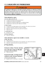
Страница 322: ...ra Asegurarse de que el equipo se encuentre en perfectas condiciones de ejercicio en todo momento En caso de observar eventuales mal funcionamientos o probables situaciones de peligro detenerinmediata...

Страница 323: ...cero aleaci n Llantas de canal invertido Bloqueo interno externo con garras de acero Destalonado Ruedas est ndar Ruedas bajas Desmontaje Ruedas est ndar con protecciones de pl stico para torreta y pal...

Страница 324: ...___ _____________________________________________________________________ _____________________________________________________________________ ________________________________________________________...

Страница 325: ...JE 344 4 MONTAJE 345 5 LEVANTAMIENTO DESPLAZAMIENTO 347 5 1 ESPACIO DE INSTALACI N 348 6 DESCRIPCI N M QUINA 349 6 1 POSICI N DEL OPERADOR 350 7 DIMENSIONES MM 350 8 ELEMENTOS PRINCIPALES DE FUNCIONAM...

Страница 326: ...FUNCIONALES 379 10 2 D POSICIONAMIENTO ADHESIVOS 379 10 2 E DESMONTAJE MONTAJE NEUM TICO 380 10 3 HSA 21 381 10 3 A INSTALACI N 381 10 3 B DATOS T CNICOS 381 10 3 C PARTES FUNCIONALES 381 10 3 D POSIC...

Страница 327: ...ada sobre el equipo los procedimientos y el mantenimiento La letra cursiva hace referencia a partes espec ficas del presente manual que ofrecen informaci n adicional o aclaraciones Se deben leer dicha...

Страница 328: ...casodeejecuci nincorrectadelosprocedimientosdemantenimientosuministrados en el presente manual o incumplimiento de las dem s instrucciones contenidas en el mismo podr anproducirseaccidentes Enelpresen...

Страница 329: ...y llantas Mantener a distancia a las personas presentes PELIGRO 7 Peligro de aplastamiento Presencia de partes m viles El contacto con partes en movimiento puede causar accidentes Est permitido el us...

Страница 330: ...m ticospocoapoco controladoalmismotiempolapresi n elneum tico lallantayeltal n NOsuperarnuncalosl mitesdepresi nindicadosporelfabricante 15 Este equipo presenta partes internas que si se exponen a vap...

Страница 331: ...e no se usa o por el mantenimiento de la m quina o de la instalaci n neum tica del taller puede dejar los actuadores neum ticos bajo presi n Descargar la instalaci n neum tica de la m quina accionando...

Страница 332: ...V O P E L I G R O AUTOCENTRANTE 11 446435 ADHESIVO PELIGROTORRETA 12 446434 ADHESIVO PELIGRO DE CHOQUECOLUMNATRASERA NO DETENERSE DETR S DE LA M QUINA 13A 461931 ADHESIVO PELIGRO DE INFLADO 13B 462778...

Страница 333: ...N X XXXXXXXX XX XX XXXXXXXXX QUAL SYS CERTIFIED ANNO DI COSTRUZIONE MANUFACTURED Mod V A kW Hz Ph bar psi ADHESIVO MATR CULA MODELO 24 463509 ADESIVO VUELCO COLUMNA 439213 ADHESIVO APERTURA CIERRE AUT...

Страница 334: ...ne S 424 S 421 S 521 S 524 Manual Operador 1 2 3 4 5 6 7 9 10 11 12 13A 14 16 17 21 22 23 24 25 26 25 12 11 10 Startline S 524 Startline S 521 12 12 25 25 5 6 23 1 3 24 2 4 7 21 9 16 17 26 11 11 10 13...

Страница 335: ...Startline S 424 S 421 S 521 S 524 Manual Operador 335 E 13B 13C Startline S 421 Startline S 424 2 24 2 7 21 4 1 3 3 13A 10 10 26 17 17 16 11 9 22 21 4 7 1 24 9 16 26 5 6 23 10 11 13B 10 14 27 5 6 23...

Страница 336: ...1 Peligro de aplastamiento destalonador parte n 446442 Peligro recipiente bajo presi n parte n 425211A Peligro de descarga el ctrica parte n 461931 Peligro de inflado parte n 462778 Peligro de inflado...

Страница 337: ...Terminal de conexi n a tierra parte n 462081A Peligro de aplastamiento manos 450005 TRAS ADVERT DE SEGURIDAD Debe aplicarse cerca de al desmontadora de neum ticos en una posici n visible para el opera...

Страница 338: ...cas Asegurarsedequelapresi ndisponibleylasprestacionesdelainstalaci ndeairecomprimido seancompatiblesconlasqueserequierenparaelcorrectofuncionamientodelam quina ver la secci n Datos t cnicos Para el c...

Страница 339: ...a monof sico 115 230 10 Volt 50 60Hz trif sico 230 400 10 Volt 50 60Hz DV 230 10 Volt 1ph 50 60Hz Ancho llanta Startline S 421 Startline S 424 de 4 a 13 Ancho llanta Startline S 521 da 4 a 14 Ancho ll...

Страница 340: ...i n esta no puede ser utilizada de manera fiable para establecer si se requieren o no ulteriores precauciones Los factores que determinan el nivel de exposici nalosqueest sujetoeloperadorcomprendenlad...

Страница 341: ...ISTO DE LA M QUINA Esta m quina debe ser usada exclusivamente para montar o desmontar neum ticos para veh culos de en las llantas con las herramientas con la que est dotada Cualquier otro uso se consi...

Страница 342: ...ren en perfectas condiciones y eficiencia y que no haya cuerpos extra os o detritos trapos herramientas etc dentro de la m quina o en proximidad de la misma que podr an afectar el funcionamiento Estos...

Страница 343: ...es embalaje ancho 910 mm profundidad 1150 mm altura 1000 mm Peso con embalaje Versi n est ndar 250 kg Versi n TI 260 kg Condiciones del ambiente de transporte y almacenamiento de la m quina Temperatur...

Страница 344: ...la m quina del pallet asegurarse de que se hayan retirado del mismo los siguientes elementos indicados a continuaci n ATENCI N Liberar la m quina de la parte superior del embalaje asegurarse de que n...

Страница 345: ...fijarlo con el anillo seeger M fig 5A Conectar el tubo G Fig 5D al empalme intermedio conectado al grifo levanta palo H Startline S 521 Registrar la posici n a ambos lados de la columna El juego entr...

Страница 346: ...uelco Fig 5M la velocidad de vuelco de la columna debe ser ajustada a no m s de 0 71 rad s Despu s de muchos ciclos de vuelco en el tiempo podr a ser necesaria una nueva calibraci n Ajustar las v lvul...

Страница 347: ...ado en la columna A fig 6D Montar la v lvula de seguridad B Fig 6D Conectar el tubo G a la v lvula Fig 6E Volver a montar el cap lateral N Fig 6A 5 LEVANTAMIENTO DESPLAZAMIENTO Para la extracci n de l...

Страница 348: ...ODEINCENDIO Noutilizarlam quinaen reasenlascuales podr aquedarexpuestaavaporesinflamables gasolina solventesparapinturas etc No instalar la m quina en una zona estrecha o posicionarla debajo del nivel...

Страница 349: ...o la rueda en posici n vertical para el destalonado y horizontal para el montaje y desmontaje Los accionamientos son realizados por el operador mediante unos pedales Cada m quina se suministra con una...

Страница 350: ...nflado 9a 9b Antes de retirar la m quina del pallet asegurarse de que se hayan retirado del mismo los siguientes elementos indicados a continuaci n ATENCI N RIESGODELESIONESPORAPLASTAMIENTO Elvuelcode...

Страница 351: ...ar perfectamente el correcto funcionamiento de cada mando de la m quina Para evitar accidentes y lesiones el equipo debe ser instalado adecuadamente se debe accionar de manera correcta y someter al ma...

Страница 352: ...entido contrario a las agujas del reloj 11 Paleta destalonadora paleta m vil para separar el tal n de la llanta 12 Grupo filtro Regulador Lubricador grupo para regular filtrar deshumidificar y lubrica...

Страница 353: ...ne S 424 S 421 S 521 S 524 Manual Operador 353 E 2 1 19 3 5 6 14 8 4 7 9 10 11 13 12 18 22 8 1 2 3 16 17 15 20 17 21 14 22 1 2 3 24 12 23 25 26 5 6 10 9 11 13 3 17 21 27 Startline S 521 S 524 Startlin...

Страница 354: ...6 10 9 11 13 3 17 27 28 16 15 PELIGRO DE EXPLOSI N Para las caracter sticas t cnicas advertencias mantenimiento y cualquier otra informaci n relativa al dep sito del aire opcional el manual de uso y...

Страница 355: ...CHOQUE El vuelco del brazo operativo puede crear un peligro potencial de colisi n con partes del cuerpo La operaci n de vuelco debe realizarse en la posici n B ATENCI N ATENCI N 12a 12b EVITAR DA OS...

Страница 356: ...ndividuar el ancho mayor B y el menor C El neum tico debe ser montado o desmontado con la rueda en el autocentrante y el lado de la anchura menor C hacia arriba RUEDAS ESPECIALES Ruedas con llantas de...

Страница 357: ...TENCI N Pulsar el pedal A Fig 14B Startline S 521 S524 Fig 14AStartlineS424 S421 yllevarlo alaconfiguraci ncompletamenteabajo Enesta configuraci n las garras est n completamente cerradas Desinflarcomp...

Страница 358: ...Fig 15A Startline S 524 Para ruedas extremadamente anchas m s de 350 mm colocar el tope B como se muestra en la figura 15B Colocar la rueda como se muestra en la fig 16 y acercar la paleta del destal...

Страница 359: ...smontaje y evitar que se da en los talones fig 17 9 4 BLOQUEO RUEDA Mantener las manos y otras partes del cuerpo alejadas de las partes en movimiento de la m quina durante la manipulaci n de las cu as...

Страница 360: ...tocentrante PisarelpedalD paraabrircompletamentelasgarrasdelautocentrante Fig 18D Cuandolam quinaest completamenteparadaydesconectadadelared desenroscar el pasador de bloqueo A Fig 18E y tornillo de f...

Страница 361: ...La regulaci n de los di metros 11 24 o 13 27 mediante el dispositivo de ajuste se debe realizar cuando el autocentrante est completamente parado y sin operar en los mandos ATENCI N Startline S 424 S 5...

Страница 362: ...a de las garras cuando un hombre est presente y luego detenerlas en la posici n deseada Sisebloquealallantadesdeelexterior Fig 19b preposicionarlascu asdebloqueoconlaayudade las referencias de di metr...

Страница 363: ...tline S 521 Pisar el pedal para volver a colocar lacolumnaenlaposici ndetrabajo Fig 21 Tirar del pulsador de posici n Z para desbloquear los brazos vertical y horizontal contempor neamente fig 22A Des...

Страница 364: ...mediante el volante B Fig 24A hasta que se haya creado una distancia de unos 2 mm entre la torreta y la llanta B Fig 23A Bloquearelbrazoverticaloperandoenlapalanca A Fig 24 9 5 c DESMONTAJE RUEDA Ins...

Страница 365: ...o el pedal de accionamiento Para la rotaci n en la direcci n opuesta simplemente levantar el pedal Levantarelsegundotal nmanualmentesobre el cabezal y girar el plato autocentrante en el sentido de las...

Страница 366: ...gan rebabas afiladas en los orificios de la v lvula Comprobar que el neum tico est en buenas condiciones y que no haya da os PELIGRO Antes de iniciar las operaciones de montaje lubricar los talones fi...

Страница 367: ...DE MONTAJE Y DESMONTAJE DE NEUM TICOS UHP APROBADOS Y RUN FLAT Para una descripci n detallada del procedimiento de montaje desmontaje de los neum ticos UHP y RUN FLAT consultar las instrucciones del...

Страница 368: ...xcesivamente inflados pueden explotar causando la dispersi n en el aire de detritos que pueden provocar accidentes 2 Los neum ticos y llantas que no tienen el mismo di metro se consideran no correspon...

Страница 369: ...resa dentro de la misma o si la llanta o el neum tico son defectuosos o est n da ados Nunca superar la presi n recomendada por el fabricante del neum tico La desmontadora de neum ticos no es un dispos...

Страница 370: ...ocederconlasoperacionesdescritas asegurarsedequenohayasuciedad polvo u otras impurezas cerca de las boquillas de inflado Se recomienda el uso de gafas protectoras ATENCI N Comprobarqueambostalonessupe...

Страница 371: ...yunallantaquenopresentenelmismo di metro por ejemplo neum tico de 16 pulgadas y 1 2 con una llanta de 16 pulgadas ATENCI N Pisar a fondo brevemente el pedal de inflado fig 36 El neum tico se expande y...

Страница 372: ...e neum ticos porpersonalcualificadoyautorizadoporelfabricante Lainstalaci nporpartedepersonal NO cualificado resultar en la p rdida de las garant as de prestaciones del dispositivo El accesorio s lo s...

Страница 373: ...reguladordesmontadora de neum ticos conectar el conector en Y y el tubo de 8 suministrado conect ndolo con el regulador del Helper Conectar el conector en Y con el regulador de la desmontadora de neum...

Страница 374: ...270 mm 270 mm Carrera brazo 350 mm 350 mm 10 1 d Partes funcionales 1 Columna vertical 2 Soporte deslizante 3 Pie de apoyo ajustable 4 Prensa tal n 5 Mando helper 6 Brazo neum tico prensador 7 Herrami...

Страница 375: ...ldelarueda colocar la rueda sobre el plato autocentrante previamentedestalonado posicionarelbrazo conelconoencorrespondenciaconelorificio centraldelallanta fig 46 accionarlav lvula de manera que presi...

Страница 376: ...ganchado a la llanta Enestoscasos utilizareldiscointroduci ndolo entre el tal n inferior y la llanta fig 51 pisar el pedal de rotaci n y levantarlo El desmontaje del segundo tal n se puede realizar de...

Страница 377: ...aje Accionarlapalancadesubida liberarlarueda del rodillo y del prensa tal n 10 2 HSU 24 10 2 a Instalaci n Instalar la base fija 1 fig 54 en la parte superior de la columna montar el final de carrera...

Страница 378: ...0 fig 59 Instalar el soporte accesorios en la parte trasera de la desmontadora de neum ticos con 2 tornillos M8x25 fig 60 Ajustar el centrado como se muestra en la fig 61 instalar el cono y centrarlo...

Страница 379: ...Manopla bloqueo G Rodillo prensador H Fijaci n accesorios I Cono corto J Cono largo K Disco levanta tal n L Perno de bloqueo F Rodillo prensador N Brazo prensador O Perno desbloqueo rotaci n P V lvul...

Страница 380: ...quear el conjunto con el pedal del autocentrante fig 66 Desbloquear el brazo del conjunto operando en el mando y retirando el cono Bloquear la rotaci n de los brazos en la posici n deseada fig 67 pres...

Страница 381: ...nuevopernodobleconarandelaytuerca Fig 72 Fijar el brazo prensador en la parte superior con una arandela y una tuerca Fig 73 Conectar el tubo aire alimentaci n 10 3 b Datos t cnicos HSA21 Fuerza cilind...

Страница 382: ...rtline S 424 S 421 S 521 S 524 Manual Operador 1 2 3 10 3 d Posicionamiento adhesivos Ref C digo Descripci n 1 Placa mando desbloqueo 2 4 405458 Adhesivo dimensi n 3 462081 Adhesivo peligro de aplasta...

Страница 383: ...Startline S 424 S 421 S 521 S 524 Manual Operador 383 E 10 3 e Desmontaje Montaje neum tico Desmontaje A B C...

Страница 384: ...384 Startline S 424 S 421 S 521 S 524 Manual Operador Montaje...

Страница 385: ...robar las conexiones del cable en el enchufe El motor no gira Controlar los microinterruptores de los pedales solo para motor inversor Controlar el mando rotaci n motor de los pedales Sustituir la tar...

Страница 386: ...lindro destalonador Despu s del bloqueo la torreta herramienta no se levanta o se eleva demasiado de la llanta Placa bloqueo no regulada Regular placa Durante el vuelco del palo los brazos horizontal...

Страница 387: ...egresa al 0 Man metro defectuoso o da ado Sustituir el man metro El lubricador no lubrica Falta aceite en el lubricador Llenar con aceite SAE20 no detergente en el lubricador Lubricador roto Sustituir...

Страница 388: ...el pomo en posici n extra da y gir ndolo al final del ajuste llevar de nuevo el pomo a la posici n de bloqueo empuj ndolo hacia abajo fig 42a La regulaci n del caudal de lubricante se ajusta girando e...

Страница 389: ...524 Manual Operador 389 E Limpiar con un pa o seco Evitar el contacto con disolventes NOTA para las indicaciones de advertencia sobre el aceite consultar el cap tulo correspondiente en el manual de u...

Страница 390: ...el ctricas electr nicas pl sticas y ferrosas Luego proceder con la eliminaci n diversificada prevista por la normativa vigente 14 INFORMACI N MEDIOAMBIENTAL El siguiente procedimiento de eliminaci n s...

Страница 391: ...ciclar el embalaje interno y externo con el que se suministra el producto y eliminar correctamente las bater as usadas solo si se entregan con el producto Con la ayuda de todos se puede reducir la can...

Страница 392: ...uertesconcentracionesdevaporesonieblas trasladar a la persona afectada al aire libre y luego al ambulatorio Ojos mojarabundantementeconaguaydirigirselom sr pidoposibleauncentrosanitario Piel lavar con...

Страница 393: ...resistencia a la abrasi n y agarre en condiciones secas y h medas as como condiciones de funcionamiento silenciosas 2 Borde o refuerzo Se trata de un inserto de metal o tejido colocado en la parte ex...

Страница 394: ...adelapartesuperiordeltal nyseutiliza comoreferenciaparacomprobarelcorrectocentradodel neum tico en la llanta despu s del montaje 7 Bordillo de protecci n Es un relieve circunferencial situado en la zo...

Страница 395: ...pecial impermeable llamado liner Esto ayuda a asegurar la estanqueidad del aire presurizado contenido en la carcasa Este tipo de neum tico debe montarse en llantas espec ficas directamente sobre las q...

Страница 396: ...imiento externo Gonfiatubeless Sistemadeinfladoquefacilitaelinflado de neum ticos tubeless Entalonado Esta operaci n se obtiene durante la fase deinfladoygarantizauncentradoperfectoentreeltal n y el b...

Страница 397: ...Startline S 424 S 421 S 521 S 524 Manual Operador 397 E 18 ESQUEMA EL CTRICO GENERAL...

Страница 398: ...398 Startline S 424 S 421 S 521 S 524 Manual Operador...

Страница 399: ...Startline S 424 S 421 S 521 S 524 Manual Operador 399 E...

Страница 400: ...400 Startline S 424 S 421 S 521 S 524 Manual Operador 19 ESQUEMA INSTALACI N NEUM TICA 70 20X262 70 20X262 186 20X150 70 20X310 70 20X310 186 20X150...

Страница 401: ...Startline S 424 S 421 S 521 S 524 Manual Operador 401 E Notas...

Страница 402: ...tandards and Directives mentioned above valid only for EC marked machines Fra D clarons que le materiel objet de cette d claration dont nous avons labor le livret technique restant en notre pos sossio...

Отзывы: