


37
English
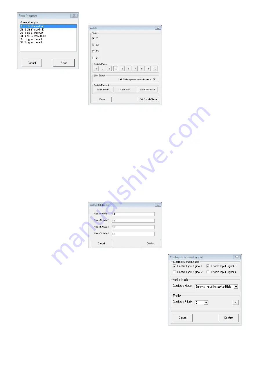
Fig. 35 Window “Read Program”
2) Select a configuration from the list under
“Memory Program” .
3) Click the button “Read” to load the con-
figuration selected or click “Cancel” to
cancel the procedure .
If a free storage location (“Program
Empty”) is selected, an error message will
appear .
4) In the dialog window “Read Program –
Overwrite current editing, are you sure?”,
confirm or cancel the procedure .
After the loading procedure has been
completed, the window “Read Program”
disappears .
6.13.5 Extra configurations
Four additional configurations (“extra config-
urations”) may be saved on the DRM-882LAN .
They can be retrieved via switching signals at
the inputs INPUT PORT (13) (
☞
The procedures for saving the extra con-
figurations on the unit and loading them from
the unit are identical to those described in the
two previous chapters; however, the buttons
“Store” and “Read” in the section “Extra Pro-
gram” are used .
6.14 Switching outputs
To set the switching outputs, click the button
“Switch” located on the upper right of the
configuration window . The dialog window
“Switch” (fig . 36) is displayed . The upper
section of this dialog window indicates the
switching status of the four switching out-
puts . A tick in the box next to the name of a
switching output indicates that the switching
output is activated . To change the switching
status, click the corresponding box .
The second section of the dialog window
provides the buttons
1
–
⓾
that allow the
user to switch between the ten savable switch
presets . A tick in the box next to “Link Switch
preset to Audio preset” will link the switch-
ing combination saved on the unit with the
corresponding unit configuration (program) .
If, for example, a configuration is retrieved by
button PRESET 3, the unit will automatically
switch to switching combination 3 .
The switching combinations 7 to 10
are linked to the extra configurations 1 to 4
(
☞
chapter 6 .13 .5), i . e . they are retrieved via
the switching inputs INPUT PORT (13) .
Fig. 36 Window “Switch”
6.14.1 Renaming switching outputs
The names of the switching outputs are fac-
tory-set to “S1” to “S4” . These names may
be changed, e . g . to indicate the function of
the units controlled . To change the names of
the switching outputs:
1) Click the button “Edit Switch Name” . The
dialog window “Edit Switch Name” is dis-
played (fig . 37) .
2) Overwrite the names of the desired switch-
ing outputs in the corresponding input
fields (max . 16 characters) .
3) Click “Confirm” to confirm the procedure
or click “Cancel” to cancel it .
The names entered will be saved on the com-
puter .
Fig. 37 Window “Edit Switch Name”
6.14.2 Saving a switching combination
on the unit
1) Use the buttons
1
–
⓾
to select the
switching combination to be saved .
2) Under “Switch”, click the boxes to switch
on /off the switching outputs as desired .
3) Click the button “Store to device” .
A message appears confirming that the
switching combination has been saved on
the selected storage location of the DRM-
882LAN .
6.14.3 Saving a switching combination
on the computer
1) Use the buttons
1
–
⓾
to select the
switching combination to be saved .
2) Click the button “Save to PC” . The dialog
window “Save As” is displayed .
3) Enter the file name desired, select the
location where the file is to be saved and
then save the file .
By default, the subfolder “Preset” is selected
which was automatically created during pro-
gram installation . The file extension * .swc
is automatically appended to the file name
entered .
Note:
Only the switching statuses are saved and
not the number of the combination, i . e . the switch-
ing statuses saved can later be loaded into another
switch preset .
6.14.4 Loading a switching combination
from a computer
1) Use the buttons
1
–
⓾
to select the
switching combination for which saved
switching statuses are to be loaded from
the computer .
2) Click the button “Load from PC” . The
dialog window “Open” is displayed .
3) Select the file desired and then confirm
your selection .
The switching outputs will adopt the switch-
ing statuses saved in the file .
6.15 Switching inputs
The four extra configurations saved on the
unit may be retrieved via external switching
signals . In addition, different priorities can be
assigned to the switching inputs .
1) To configure the switching inputs, click the
button “Configure” located on the right-
hand side of the window (under “Extra
Program”) . The dialog window “Configure
External Signal” (fig . 38) is displayed .
2) After the settings described in chapters
6 .15 .1 to 6 .15 .3 have been made, click
the button “Confirm” to confirm your
changes .
3) In the dialog window “Configure – Are you
sure?”, confirm or cancel the procedure .
Fig. 38 Window “Configure External Signal”