AT5762 Air Crimp Head Tool
Doc. No: ATS-640051100
Release Date: 12-10-02
UNCONTROLLED COPY
Page 2 of 6
Revision: D
Revision Date: 01-24-11
OPERATION
Refer to the instruction manual for the 19279-0001 (AT-200)
for mounting this crimp tool head.
Crimping Terminals
1.
There are 3 Tab Locator Blades supplied with the tool.
One is for .187 and .250 Tabs; one is for .205 Tabs and
.110 Tabs and a third is for LIF connectors. Make sure
the proper blade is installed on the top of the locator and
the other is stored on the bottom of the locator.
2.
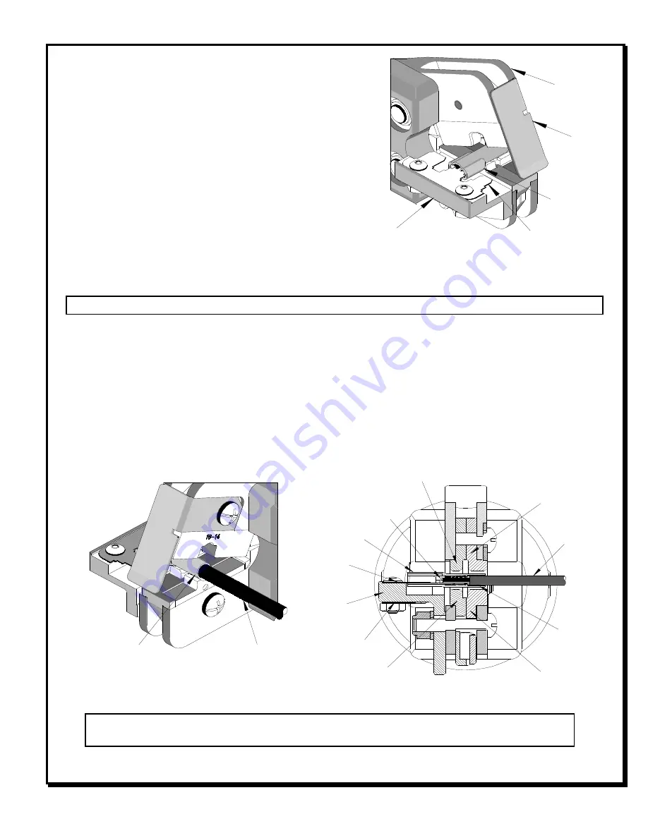
Insert the wire into the terminal. Push the terminal and
wire onto the tab locator all the way to the stop in the
proper color-coded nest. The barrel of the terminal
should be up. See Figure 1.
Caution:
Never operate this tool without the supplied safety shield in place. Never place fingers in the tool nests.
3.
Push on the wire to assure it is still fully seated in the terminal. The wires end should butt against the wire
stop stamped into each terminal. See Figure 2 and 3. Cycle the tool.
4.
Remove the crimp and inspect for proper crimp location, and check for insulation closure. Molex offers a
Crimp Inspection Handbook for closed barrel industrial product. See our website or contact your sales
engineer.
5.
If the insulation part of the crimp needs to be adjusted, first loosen the M4 screw on the bottom tool jaw and
insert a 3/32 hex wrench (supplied) into the bottom of the lower die. See Figure 4. A clockwise (CW) rotation
decreases insulation crimp while a counter-clockwise (CCW) rotation increases insulation crimp. After
adjusting retighten the M4 screw.
Note
: Whenever crimping without the locator, make sure the seam of the terminal is oriented up or
down in the tool if using unbrazed product, as this will provide higher pull force values.
TERMINAL
SAFETY
SHIELD
TAB LOCATOR
Figure 1
LOCATOR
JAWS
OPEN
2
ND
and 3
RD
TAB
LOCATOR
LOCATOR
WIRE
TERMINAL
Figure 2
TERMINAL
BARREL
TERMINAL
WIRE
CONDUCTOR PUNCH
INSULATION ANVIL
INSULATION
PUNCH
1
ST
TAB
LOCATOR
WIRE STOP BUILT
INTO TERMINAL
Figure 3
CONDUCTOR ANVIL


