


14
Part 6 Gas Conversion
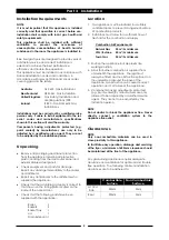
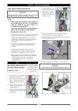
Main Burner Injectors
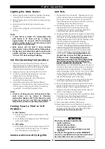
1. To remove Main
Burner Injectors (Qty
9), use a
⅝
” A/F
spanner to prevent
the Injector Mounting
Bush from turning.
2. Unscrew and remove
Main Injectors, using a
½” A/F spanner.
3. Replace with the correct size injectors.
4. Refit burner assembly back into burner box.
Pilot Burner Injectors
1. Unscrew the pilot supply tube from the pilot
burner and remove the pilot injector.
2. Determine correct sized pilot injectors for the
corresponding gas from the table overleaf.
3. Fit correct sized injector into pilot burner and
re-connect gas supply tube to the pilot burner.
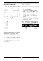
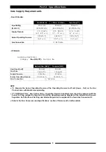
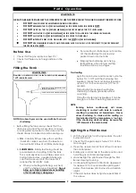
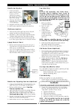
Supply Pressure Check
1. Remove the blanking screw and connect a
manometer to the Supply Pressure Test Point
(‘IN’) on Gas Control Valve.
2. Turn ‘On’ the gas supply and ensure that the
pressure is within specifications shown in ‘Gas
Specifications Table’ at rear of this section.
Main Burner Operating Pressure Adjustment
1. Connect a Manometer to Operating Pressure
Test Point (‘OUT’) on the gas control valve.
2. Remove slotted cap to reveal
Operating
Pressure Adjusting Screw
.
3. Light Main Burner and turn Operating Pressure
Adjusting Screw to obtain correct burner
pressure for type of gas being used. Refer to
Gas Specifications Table
at rear of this section.
4. Remove manometer from Operating Pressure
Test Point and refit blanking screw.
5. Refit slotted cap to screw adjustment point.
Supply Pressure
Test Point
Operating
Pressure
Test Point
Operating
Pressure
Adjusting Screw
Pilot Burner
Adjusting
Screw
Injector Mounting Bush
Injector
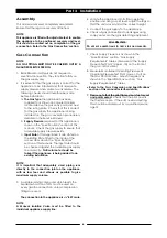
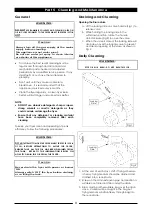
Town Gas Only
NOTE:
For Town Gas application, Gas Control Valve -
Operating Pressure Adjusting Screw should be
replaced with the Knock Out Plug supplied in Town
Gas Kit and the operating pressure adjusted at the
External Gas Pressure Regulator. Both the Knock Out
Plug and External Regulator are supplied in the Town
Gas Conversion Kit.
1. Remove slotted
cap from regulator.
2. Turn ‘On’ gas
supply and
appliance.
3. Adjust pressure
adjusting screw to
achieve correct
burner operating
pressure.
NOTE: Measure operating pressure at the Gas
Control Valve ’Out’ test point with burner operating.
4. Verify operating pressure remains correct
(Re-adjust regulator if required).
5. Screw cap nut back onto regulator.
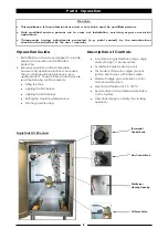
Pilot Burner Flame Adjustment
1. Once main burner operating pressure has been
set, adjust pilot burner supply so that pilot flame
impingement onto thermocouple and
thermopile is correct and main burner pilot flame
ignites main burner satisfactorily.
2. Adjust pilot flame size by adjusting
Pilot Burner
Adjusting Screw
. Pilot burner flame should be
approximately 1" long for main burner ignition.
Anti-clockwise rotation of adjustment screw will
increase size of pilot flame.
Gas Type Identification Label
On completion of gas conversion, replace gas type
identification label located at:-
- Rear of appliance, above gas connection.
- Beside the Rating Plate.
Commissioning
Before leaving the converted installation;
1. Check all gas connections for leakages using
soapy water or other gas detecting equipment.
2. Check the following functions in accordance
with the operating instructions specified in the
‘Operation’ section of this manual.
Light the Pilot Burner.
Light the Main Burner.
Check the Thermostat operation.
Ensure that all the controls operate correctly.
NOTE: If it is not possible to get the fryer to operate
correctly, shut Off the gas supply and contact the
supplier of this appliance.
WARNING:
D
O
NOT
USE
A
NAKED
FLAME
TO
CHECK
FOR
GAS
LEAKAGES
.
Pressure
Adjusting
Screw
Cap Nut