


2
3
4
AA2
AA1
AA1
AA3
1
AA1
AA4
4
5
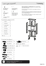
Grids Surface
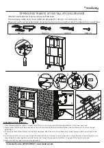
TIPPING RESTRAINTS KIT INSTALLATION GUIDANCE
AA1 x 2
AA2 x 4
AA3 x 4
AA4 x 4
Different wall materials require unique wall fasteners.
The wall plugs (AA2) and screws (AA3) are designed for fixing to concrete walls only.
Please consult your local hardware store to ensure you are using the correct hardware for you wall type.
Installation Instructions :
1. Attach bracket (AA1) securely to the back top of the furniture using screw (AA4) provided. Allow 8 - 10 cm from each side.
2. Please make a hole for wall plugs position on the wall and minimum 15 mm below bracket secured to the back of unit attach the wall
plugs (AA2).
3. Locate the other bracket (AA1) on the wall over wall plugs (AA2). Place furniture into position so both brackets (AA1) are vertically in the
line.
4. Lace the end of the restrains strap through the larger hole in each bracket. Ensure the restrains strap with grids surface facing the inner
loops. Bring both ends together and slide the flat end through the locking end and draw it through until all slack is removed.
5. Make sure that the strap is securely laced & locked.
Customer Service 609.256.9000 | www.modway.com


