FH-W1811-5
Aviator Flush Instructions 19
8A
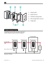
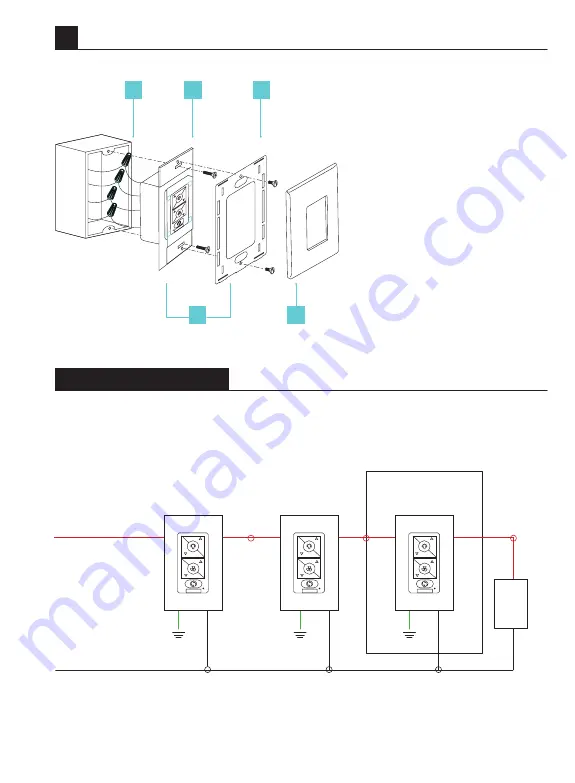
Multi-location wiring
1
2
3
5
4
1. Wall Outlet
2. Wall Control
3. Wall Mounting Plate
4. Mounting Plate Screws
5. Wallplate
Individually pair each of the wall controls with the fan
receiver using the pairing instruction. See page 22.
Line/Hot
Red
Green (Green or Bare)
Wallcontroller 1
Wallcontroller 2
Wallcontroller 3
If Applicable
FAN
Neutral/White
Wall Control 1
Wall Control 2
Wall Control 3
Содержание Aviator 5 Flush
Страница 1: ...Aviator 5 Flush Installation Instructions works with the Google Assistant ...
Страница 11: ...FH W1811 5 Aviator Flush Instructions 11 1 1A 1B 2 2 1 2 2 3 1 Support Brace 2 Outlet Box 3 Joist ...
Страница 13: ...FH W1811 5 Aviator Flush Instructions 13 3 4 3A 5 ...
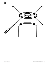
Страница 17: ...FH W1811 5 Aviator Flush Instructions 17 7 ...
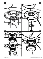
Страница 21: ...FH W1811 5 Aviator Flush Instructions 21 9 9B 9C 9A ...
Страница 27: ...FH W1811 5 Aviator Flush Instructions 27 ...
Страница 34: ...FH W1811 5 Aviator Flush Instructions 34 ...
Страница 35: ...FH W1811 5 Aviator Flush Instructions 35 ...
Страница 36: ...modernforms com FH W1811 5 ...


