page 5 of 5
Description of operation
Bringing into service
After assembling the Loco Controller DHR-PIC can be hot-plugged
to any of the model railway’s SX-bus jacks.
At start-up the start screen indicating the software version of the
Loco Controller DHR-PIC is displayed for a few moments.
Then it is switched to the menu
Selection of a locomotive
where you enter the address and digital format for the locomotive
to choose.
Signs and symbols
In these instructions the following symbols are used:
symbol name
Explanation
ZE
Press button ZE.
Turns on and off the power of the rails
Lok
Press button Lok.
Opens the menu
selection of locomotives
Li
Press button “light”
Switches on and off the loco light
F
Press button F
Activates second loco function
< >
Press button “<>”
Changes direction of travel of the loco
Push
Press rotary switch
Confirm selection (function varies)
Turn
Turn rotary switch
Change selection (function varies)
Link to other section of these instructions
Selection of a locomotive
When switching to the locomotive selection menu, the format and
the address of the locomotive are chosen.
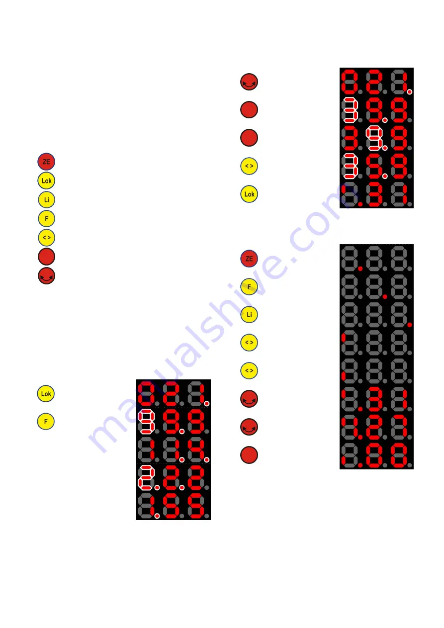
In the following pictograms blinking is represented by a white
hollow.
Selection of digital format
The selected digital format is indicated by blinking points whereas
the numbers indicate the address of the locomotive (of the se-
lected format)
Change to menu selection of
a locomotive
(last used loco (here SX1) is
displayed)
Changes to another digital
format
(here: Selectrix-2)
DCC, short addresses:
center and right points blink
DCC, long addresses:
left and center point blink
Motorola (MM new):
left point blinks
Selection of an address
After the selection of the digital format the address of the locomo-
tive can be chosen.
Blinking numbers highlight the current position which is being
changed.
Iterates addresses in single
steps (only available for
Selectrix-1, DCC (short) and
Motorola)
Switch to mode of entering
address of locomotive digit
by digit
Switch to right next position.
(Confirms selection at right
most position)
Move one position to the left
(e.g. to correct address).
Quit selection menu.
The last displayed address
can now be controlled.
Controlling locomotives
In normal driving mode where one loco is selected (
Selection of
a locomotive), the following control actions can be carried out and
are displayed as show in the pictograms:
Switch on or off
the power on the rails
Turn on and off
second loco function
Turn on and off
light
Changes direction of travel of
the loco
(here: forwards)
Changes direction of travel of
the loco
(here: backwards)
Change loco speed
(here SX1-Loco: max. 31
speed steps, forwards)
Change loco speed
(here SX2-Loco: max. 127
speed steps, forwards)
Reset speed to 0 and change
direction of travel
If the selected locomotive is controlled by a second controller (e.g.
second loco controller or central unit), changes are immediately
indicated on the display.
All brands and trademarks are property of their respective owners.
Modellbahn Digital Peter Stärz, Dresdener Str. 68, D-02977 Hoyerswerda, Germany
Illustrations and technical data are subject to change.
We are not responsible for printing or typographical errors.
Printable version of 17.06.2019


