MKS HPS 937A Series Скачать руководство пользователя страница 1

HPS

TM

 Series 937A

High Vacuum

Multi-Sensor System

OPERATION AND

MAINTENANCE MANUAL

Содержание HPS 937A Series

Страница 1: ...HPSTM Series 937A High Vacuum Multi Sensor System OPERATION AND MAINTENANCE MANUAL...

Страница 2: ......

Страница 3: ...August 1998 Part 100009273 Rev 4 0 HPSTM Series 937 A High Vacuum Multi Sensor System...

Страница 4: ...k of Alconox Inc Baratron is a registered trademark of MKS Instruments Inc Elgiloy is a registered trademark of Elgiloy Co HPS and IgniTorr are trademarks and I MAG is a registered trademark of MKS In...

Страница 5: ...4 Definitionen der am Ger t angebrachten Symbole Deutsch 5 S mbolos que Aparecen en la Unidad Espa ol 5 Safety Precautions 6 Safety Procedures and Precautions English 6 Sicherheitsvorschriften und Vor...

Страница 6: ...dard Configuration Codes 40 Setup Review Screen 2 41 Setup Review Screen 3 41 Setup Review Screen 4 42 Setup Review Screen 5 42 Setup Review Screen 6 42 Setup Review Screen 7 43 Pressure Mode 43 Cold...

Страница 7: ...IES 937A SENSOR A 1 Cold Cathode Sensors A 1 General A 1 Locating a Cold Cathode Sensor A 1 Orienting a Cold Cathode Sensor A 1 Managing Contamination in a Cold Cathode Sensor A 2 Testing a Cold Catho...

Страница 8: ...ng the Baratron Capacitance Manometer A 17 Thermocouple Sensor A 18 General A 18 Orienting the DV 6M Sensor A 18 Connecting the DV 6M Sensor A 18 Cleaning the DV 6M Sensor A 19 APPENDIX B LEAK TESTING...

Страница 9: ...f an optional communications module was ordered a separate manual for the module should also be included with the package The Series 937A System s sensors and their connecting cables are sold separate...

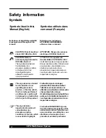
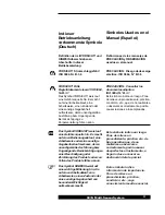
Страница 10: ...hlight D finition des indications ATTENTION et REMARQUE utilis es dans ce manuel ATTENTION Risque de secousse lectrique ISO 3864 No B 3 6 ATTENTION Se reporter la documentation ISO 3864 No B 3 1 L ind...

Страница 11: ...f eine wichtige Mitteilung hin die auf einen Arbeitsablauf eine Arbeitsweise einen Zustand oder eine sonstige Gegebenheit von besondererWichtigkeit aufmerksam macht Definiciones de los mensajes de PRE...

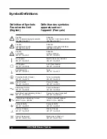
Страница 12: ...IEC 417 No 5020 Mat riel de la Classe II IEC 417 No 5172 a Caution refer to accompanying documents ISO 3864 No B 3 1 Caution risk of electric shock ISO 3864 No B 3 6 Caution hot surface IEC 417 No 504...

Страница 13: ...IEC 617 2 N 020206 Equipotencialidad IEC 417 N 5021 Caja o chasis IEC 417 N 5020 Equipo de clase II IEC 417 N 5172 a Vorsicht Bitte Begleitdokumente lesen ISO 3864 Nr B 3 1 Vorsicht Stromschlaggefahr...

Страница 14: ...onductive parts including knobs and controls that may appear to be insulating can render an electrical shock Do not substitute parts or modify instrument Do not install substitute parts or perform any...

Страница 15: ...not remove instrument covers Component replacement and internal adjustments must be made by qualified service personnel only Use the proper power cord Use only a power cord that is in good condition...

Страница 16: ...e isol s peuvent tre source d une secousse lectrique Ne pas substituer des pi ces ou modifier l appareil Ne pas utiliser de pi ces d tach es autres que celles vendues par MKS Instruments Inc ou modifi...

Страница 17: ...l appareil Le remplacement des composants et les r glages internes doivent tre effectu s uniquement par un personnel d entretien qualifi Utilisation d un cordon d alimentation appropri Utiliser unique...

Страница 18: ...ndung zum Schutzleiter verloren besteht an s mtlichen zug nglichenTeilen aus stromleitendem Material die Gefahr eines elektrischen Schlages Dies gilt auch f r Kn pfe und andere Bedienelemente die dem...

Страница 19: ...g nur durch qualifizierte Fachleute Das Geh use des Instruments darf vom Bedienpersonal nicht ge ffnet werden Das Auswechseln von Bauteilen und dasVornehmen von internen Einstellungen ist nur von qual...

Страница 20: ...la conexi n protectora de puesta a tierra todas las piezas conductoras a las que se tiene acceso incluidos los botones y mandos que pudieran parecer estar aislados podr an producir descargar el ctrica...

Страница 21: ...s especializados Los operarios no deben retirar las cubiertas del instrumento El cambio de piezas y los reajustes internos deben efectuarlos nicamente t cnicos especializados Usar el cable el ctrico a...

Страница 22: ...Coordination Installation Overvoltage Category II Pollution Degree 2 Power Requirement Nominal 100 120 220 or 230 240 VAC 50 60 Hz MainsVoltage Fluctuations not to exceed 10 of nominal Power Consumpti...

Страница 23: ...angle status and error messages Pressure Units Torr mbar Pascal or microns Update Rate 50 msec per sensor or 250 msec per full set of sensors in Pressure and Leak Test modes 100 msec per sensor in al...

Страница 24: ...RS 232 and RS 485 2400 4800 9600 19200 bit rate selectable Electronic Casing Aluminum Dimensions 9 x 12 x 3 W x D x H 241 mm x 311 mm x 88 mm Size rack 2U high TypicalWeight 8 0 lb 3 6 kg CE Certific...

Страница 25: ...gs DV 6M Pressure Range CC 1 x 10 11 to 1 x 10 2 Torr 1 x 10 11 to 1 x 10 2 mbar 1 x 10 9 to 1 x 10 0 Pa 1 x 10 8 to 1 x 10 1 microns Pirani 5 x 10 4 to 4 x 10 2 Torr 7 x 10 4 to 5 x 10 2 mbar 7 x 10...

Страница 26: ...crons CM 1 to 95 of the measurement range of the head e g 1 Torr head is 1 0 x 10 2 to 9 5 x 10 1 Torr 1 3 x 10 0 to 1 2 x 10 2 Pa etc TC 2 0 x 10 3 to 9 5 x 10 1 Torr 2 7 x 10 3 to 1 2 x 10 0 mbar 2...

Страница 27: ...lver copper brazing alloy alumina ceramic Elgiloy OFHC copper Series 423 SS 302 SS 304 glass Al Inconel X 750 alumina ceramic Pirani 300 series stainless platinum alumina ceramic silver brazing alloy...

Страница 28: ...aximum BakeoutTemperature Without Controller or Cables CC Series 421 250 C 482 F when backshell subassembly removed 125 C 257 F otherwise Series 423 400 C 752 F CF flange version only with magnet remo...

Страница 29: ...ange CC 421 2 4 lb 1 1 kg 423 1 8 lb 0 8 kg Pirani 0 5 lb 0 2 kg CEP w KF Flange 0 5 lb 0 2 kg Vacuum Connection CC KF 25 KF 40 2 CF 8 VCR F 1 tubing Pirani CEP KF 16 KF 25 1 8 NPT M with compression...

Страница 30: ...22 937A Multi Sensor System Feature and Control Locations Front Panel Rear Panel 11 12 13 14 15 16 17 18 19 20 10 8 9 1 2 3 4 7 6 5...

Страница 31: ...le Male 15 pin D Accessory Connector AC Power Inlet IEC 320 Slot for optional Communications Module Analog Module UCAL Enable Disable Switch Female 25 pin D Analog Output Connector Slot CC for Cold Ca...

Страница 32: ...ng abnormal pressure and taking appropriate security measures using relay set points Controlling system pressure using the analog output as input to an automatic pressure controller Starting or stoppi...

Страница 33: ...f a sensor is turned off not connected properly or used out of range a relevant message replaces its pressure reading The Controller s Function Select rotary switch and push button labels are color co...

Страница 34: ...on the Analog Module These include buffered logarithmic and combination logarithmic output Buffered and logarithmic analog outputs are available simultaneously from all sensors A buffered analog sign...

Страница 35: ...instrument or any modules To remove a module for modification 1 Using a 1 Phillips screwdriver remove the two screws on the top and bottom of the rear panel of the module 2 Use a small flat blade scr...

Страница 36: ...cathode sensor see Analog Module page 31 Setting two jumpers on the cold cathode sensor module can make it compatible with either the Series 937A Controller or older Series 937 or Series 929 controll...

Страница 37: ...y verify the setting matches the type of head used Head refers to the full scale pressure reading of the selected sensor This pressure gives a 10V output It is always 1 0 x 10N Torr Heads calibrated s...

Страница 38: ...ill display in the unit selected If set points are set prior to a pressure unit change they must be reset Capacitance manometer heads must provide a 0 10V output with full scale range specified in Tor...

Страница 39: ...nications Module Optional The character format is 8 data bits MSB always 0 1 stop bit and either even or no parity Select a serial bit rate and protocol from the DIP switch bank SW1 on the RS 232 RS 4...

Страница 40: ...ss characters the remaining portion of a faulty command may be misinterpreted Therefore with a parity error the Controller may respond differently from what s expected To avoid this the more robust mu...

Страница 41: ...he line voltage requested If you need to change the line voltage set the jumpers for the new voltage and install fuses correspondingly The fuse holders are located adjacent to the voltage selection ju...

Страница 42: ...t of the front panel for user notations such as type and location of sensors set point values calibration status or other pertinent information Write with a standard pencil on the labels or apply prep...

Страница 43: ...error messages appear on the display after switching on the Series 937A Controller see the Error Messages section on page 64 Mounting the Series 937A controller into a 19 rack HPS Part 100005651 1 At...

Страница 44: ...n the Power switch to Off When turning the Controller off allow it to remain off for at least 5 sec before turning it back on If after turning the power on the Controller makes a periodic beeping soun...

Страница 45: ...SP3 SP4 or SP5 Set Point Relay Status indicates the corresponding set point relay is active i e pressure is below the set point value TORR mBAR PASCAL or MICRON Unit of Measure indicates selected uni...

Страница 46: ...Test mode indicates change due to a probe gas Line segments above or below the center of the bar graph indicate direction and magnitude of the deviation Using the Front Panel Controls The Controller...

Страница 47: ...us review screens The sequence and content of setup review screens are shown below Depending on the configuration of the Controller some screens may not appear Setup Review Screen 1 This screen shows...

Страница 48: ...perform steps 1 4 before proceeding with the remedies listed in the table Since the resolution of these conditions may involve more than one module it is best to carry out the following steps before a...

Страница 49: ...s on the capacitance manometer module have been set to at least one valid head selection Code Condition Remedy CC Module is configured correctly CC 8 Reject Module The high voltage supply of this modu...

Страница 50: ...lots CC and A or if the selected control sensor is missing or is unsuitable as a control sensor N O C T L C H no control channel is displayed Setup Review Screen 5 Selected time delay for a cold catho...

Страница 51: ...ssure reading when in Pressure mode are listed listed below C T L with CONTROL 1 Slot CC or CONTROL 2 Slot A Control A control sensor is reporting a pressure above the control set point and has turned...

Страница 52: ...analog ouput and set point relays continue to work To lock or unlock the front panel controls or to display the lock status 1 Set Function Select switch to Pressure mode and select the bottom display...

Страница 53: ...e bar graph and beeper for a new reference pressure At the reference pressure the beeper rate will be less than 1 Hz To leak test your system 1 Pump the system to as low a pressure as possible 2 Turn...

Страница 54: ...nd the normally closed contact is closed Reading a Relay Set Point To read the set point value 1 Turn the Function Select switch to Relay Set Points 2 Set the Gauge Select switch to the desired set po...

Страница 55: ...ease and depress the Down push button once The set point will decrement to 0 0 5 Press the Up push button to restore the set point and return it to the sensor s range Set points are factory preset to...

Страница 56: ...hen either the Function Select or the Gauge Select switch is turned to another position The new set point is not saved if the Controller is turned off before turning one of these switches Setting a Co...

Страница 57: ...rotection and Control Set Point Messages Whether a cold cathode sensor or a control sensor is selected bothcontrol and protection set points will be displayed Only the set point selected with the Gaug...

Страница 58: ...alibration mode indicating that the calibration can not be changed The UCAL Enable Disable switch does not reset a sensor to its factory calibration It simply allows or prevents changes to existing se...

Страница 59: ...layed The bar graph display is activated to indicate the difference between the sensor signal and its present zero calibration value For a capacitance manometer each segment represents 05 of full scal...

Страница 60: ...nce manometer signal is read CM ZERO and L O on the capacitance manometer s channel line both appear on the display As soon as any one of the required conditions ceases to be true auto zeroing stops a...

Страница 61: ...e new atmospheric value The pressure reading will be displayed as AA for a Pirani and H I for a thermocouple sensor The indicator U will appear next to the display of the channel A considerable atmosp...

Страница 62: ...e User Cal push button in step 4 the display will read 7 6x10 2 Torr and the indicator U will appear next to the display of the channel This method assumes the sensor is exposed to 760 Torr of air nit...

Страница 63: ...ssure to 760 2 Torr 3 Adjust the potentiometer until the pressure displayed on the front panel is 7 6x10 2 Torr Cold Cathode Operation The cold cathode sensor is turned on and off by switching the hig...

Страница 64: ...necessary to press C C Off once before pressing C C On to turn on the sensor Cold Cathode Module Remote Connector The cold cathode sensor may be turned on or off from the rear panel of the Cold Catho...

Страница 65: ...thode sensor automatically turns on again The control set point will only turn on the cold cathode sensor as the pressure falls below the set point value if it was first turn off by the control set po...

Страница 66: ...mit of the relay set point For a capacitance manometer the lower limit of the control set point is one half of the relay set point lower limit or 0 5 of full scale The upper limit for the control set...

Страница 67: ...Rate The A D converter has a conversion time of 50 msec The total pressure update cycle in either Pressure or Leak Test modes is the number of sensors multiplied by 50 msec e g if 5 sensors are operat...

Страница 68: ...us sensor conditions Pin 9 provides this function only when a cold cathode sensor is installed in slot A Pin Description 1 analog output combination channel CC 2 analog output buffered channel CC 3 an...

Страница 69: ...n to resolve the equivalent of 1 of reading in the logarithmic output If Logarithmic Output Is 0 6 to 9 6 V 0 2 V 9 8 V 10 V 10V 10V 10V 0 V Then Normal range Sensor exposed to a pressure less than in...

Страница 70: ...will be 10V The second combination output will be provided on Pin 9 if a cold cathode sensor is in Slot A and it has a valid combination sensor While the cold cathode sensor is disabled the combinati...

Страница 71: ...a checksum test If the checksum test finds an error no communications functions are possible Other Controller functions will operate normally With RS 232 communications the data output pin pin 3 of th...

Страница 72: ...eter head DIP switch setting was detected see p 29 No recognized modules are plugged into the Controller Push the Up push button to cancel the message The Controller will ignore the incorrectly config...

Страница 73: ...Hold right button and press left 4 times to show lock state Hold left button and press right once to change lock state Decrease Setup review screens sequentially Decrease Save new calibration Channel...

Страница 74: ...Thermocouple 2 0x10 3 9 5x10 1 Capacitance Manometer 1 0 FS 95 FS 1T 1 0x10 2 9 5x10 1 10 T 1 0x10 1 9 5x10 0 100 T 1 0x10 0 9 5x10 1 1000 T 1 0x10 1 9 5x10 2 10000T 1 0x10 2 9 5x10 3 Control Setpoint...

Страница 75: ...0 6 m 100002505 10 ft 3 0 m 100007873 25 ft 7 6 m 100007874 50 ft 15 2 m 100002395 Custom to 300 ft 91 4 m 100008759 Cable for 317 Convection Pirani 345 Pirani Sensor 10 ft 3 0 m 103170006SH 25 ft 7 6...

Страница 76: ...r Cold Cathode Series 421 KF 25 104210004 KF 40 104210001 2 CF 104210002 1 tube 104210003 8 VCR F 104210005 Series 423 I MAG KF 25 104230004 KF 40 104230001 2 CF 104230002 1 tube 104230003 Sensor Conv...

Страница 77: ...150014 15 mm x 30 mm Tubing 103150016 18 mm x 30 mm Tubing 103150018 Sensor Thermocouple 1 8 NPT M 100006763 HPS Products Series 937A Combination 100009273 Vacuum Sensor System User s Manual Please ca...

Страница 78: ...id service is desired if the product is contaminated with potentially corrosive reactive harmful or radioactive materials gases or chemicals When products are used with toxic chemicals or in an atmosp...

Страница 79: ...71 937A Multi Sensor System Notes...

Страница 80: ...ates the ionization process in cold cathode sensors assuring UHV pressure readings in seconds see Spare Parts and Accessories p 71 Locating a Cold Cathode Sensor Locate a cold cathode sensor where it...

Страница 81: ...sensor body Series 423 I MAG Cold Cathode Sensor ConnectingtheI MAGSensor Mount the Sensor to a grounded vacuum system If the I MAG Sensor has a CF flange remove the magnet first to allow clearance fo...

Страница 82: ...an using high quality detergents compatible with aluminum such as ALCONOX Scrub with a mild abrasive to remove most contamination Scotch Brite or fine emery cloth may be effective Rinse with alcohol C...

Страница 83: ...937A Multi Sensor System A 4 Series 423 I MAG Sensor exploded view 13 15 14 12 11 10 9 8 7 6 5 4 3 1 2...

Страница 84: ...has a concave shape Refer to the figures to see its installation orientation 6 Insert the small end of the compression spring into the sensor body 7 Using your thumbs push the larger end of the spring...

Страница 85: ...V SHV connector and Ion Current SMA connector Where stress might be applied to the cable use separate strain relief to avoid damage to the sensor cable or the Controller Cables are available from the...

Страница 86: ...7 Series 421 Cold Cathode Sensor exploded view of backshell internal and body subassemblies Backshell Subassembly Internal Subassembly Body Subassembly 11 13 14 15 16 17 18 19 20 21 22 23 25 24 26 27...

Страница 87: ...generally proceeds from bottom to top of the internal assembly drawing 6 To remove the cathode release the two integral spring loaded ears hooked over the shoulder of the ceramic insulating support 7...

Страница 88: ...so remove the backshell subassembly shown on page A 7 Follow steps 1 through 4 of Disassembling the Series 421 Sensor on page A 8 Pirani Sensors General Two types of Pirani sensor can be used with the...

Страница 89: ...e the best accuracy can be achieved above 30 Torr by calibrating the sensor oriented vertically with the port facing down The Pirani sensor can be calibrated at any pressure between 600 and 1000 Torr...

Страница 90: ...Cables are available in standard lengths of 10 25 50 and 100 feet and in custom lengths up to 500 feet The series 345 Pirani Sensor is connected to the controller using the same cable as the Series 31...

Страница 91: ...ct calibration but the tube may still be functional The most common cause of Sensor failure is a broken filament checked from pin 4 to pin 6 due to improper handling Test the Sensor with an ohmmeter w...

Страница 92: ...seal Positive pressures might blow the Sensor out of a compression fitting damaging equipment and possibly injuring personnel Do not use a compression mount quick connect to attach the Sensor to a sy...

Страница 93: ...he Controller Cables are available from HPSTM in standard lengths of 10 25 50 and 100 feet and in custom lengths up to 500 feet Some applications may require the use of special cables such as where th...

Страница 94: ...m the end of the Sensor as shown below 2 Check the resistance on the Sensor s pins listed in the first column on the table below Test the Sensor with an ohmmeter with less than 5 mA of current The res...

Страница 95: ...ecommended Any standard vacuum fitting may be used VCR compression KF flange etc The sensor port will easily carry the weight of the transducer Due to the failure of many users to follow the proper ti...

Страница 96: ...r Repair by the user is not recommended since replacement or movement of PC board components may require complete calibration of the unit Return to MKS for repair BaratronType 622A shielded cable with...

Страница 97: ...NPT do not use the case for tightening The Sensor s vacuum tubing has 9 16 hex flats for tightening Wrap about two turns of Teflon tape on the threads of the Sensor in the direction of the threading t...

Страница 98: ...luids condensing or decomposing on the heated filament can contaminate the Sensor This changes the emissivity of the filament which in turn can cause the calibration to change especially at low pressu...

Страница 99: ...system For optimal sensitivity select a probe gas with the largest difference between its molecular weight and that of the system gas A gas different than the system gas entering through a leak will...

Страница 100: ...If the above leak detection method fails to indicate the location of a leak unexpected high pressures may be caused by a virtual leak i e outgassing of a system component You can locate outgassing pa...

Страница 101: ...421 and 423 When using the graphs remember that the pressure scale is always logarithmic and the voltage scale is linear for all sensors except the capacitance manometer Equal increments of distance a...

Страница 102: ...937A Multi Sensor System C 2 10 4 10 3 10 2 10 1 100 10 1 10 2 10 3 Pressure Torr 10 8 6 4 2 0 Output Voltage VDC He N2 Ar Buffered Analog Output Pirani Series 315 and 345...

Страница 103: ...937A Multi Sensor System C 3 10 3 10 2 10 1 1 10 1 10 2 10 3 10 8 6 4 2 0 Pressure Torr Output Voltage VDC He Ar N2 Buffered Analog Output Convection Pirani Series 317...

Страница 104: ...A Multi Sensor System C 4 Buffered Analog Output Capacitance Manometer 10 1 0 1 0 01 Output Voltage VDC 10 3 10 2 10 1 1 10 1 10 2 10 3 10 4 Pressure Torr 1 10 100 1000 10 000 Head Full Scale Range To...

Страница 105: ...937A Multi Sensor System C 5 Buffered Analog Output Thermocouple DV 6M 10 9 8 7 6 5 4 3 2 1 0 Output Voltage 10 4 10 3 10 2 10 1 1 10 1 Pressure Torr...

Страница 106: ...lti Sensor System C 6 10 4 10 3 10 2 10 1 1 10 1 10 2 10 3 10 4 10 5 10 6 10 7 10 8 10 9 10 10 10 11 0 1 2 3 4 5 6 7 8 9 10 N 2 Pressure Torr Output Voltage VDC Logarithmic and Combination Output All...

Страница 107: ......

Страница 108: ......

Отзывы: