Adaptor
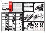
Assembly
11
Cabling Back Boxes
Assembly of Covers
continued
Complete
Assembly
(fi xing screws optional)
12
13
5
Flat
Angle
218 mm
133 mm
Fix screws
top & bottom
Allow 3 mm for cover
133 mm
to centre
of main
carrier
Cabling
External Corner
Data Sweep
Hinged Lid Cable Tray
Cable Retainers
Screening
Assembly
(optional)
The covers can be
further secured,
by using the screw
fi xing kit
9
8
8
10
Assembly of Covers
Covers to be
cut back when
interfacing
with fi ttings
KEY:
Power
Data
Screening
Assembly
(optional)
6B
Mounting Back Boxes
For conduit
20 mm and 25 mm
drill appropriate size
Cut out
markings
7
6A
Maintain
power cable
segregation
behind box
Cut screening
divider to length
and lay in upper
or bottom
compartment
as shown
Only remove
knockouts where
appropriate
Fit screening cable to
tag of screening divider
Remove appropriate
knockout as required
OR
Screening divider shown on
top compartment only for clarity
For cable capacity refer to Catalogue
or MK Technical Sales Service dept.
Steel
PVC
Must be
suitably
earthed
Knockout for Data
For YT2 and YT4
cut appropriate size
OR
90º +/-5º
90º +/-5º
96mm
170mm
min. column size
50mm
12mm
76mm
To release back box from
trunking - lift tab
Crossover
(185 mm for VP196)
(268 mm for VP196)
(185 mm for VP196)


