background image

satellite speakers

page 2

1. INTRODUCTION...........................................................................................................3
2. PLACEMENT OF YOUR SATELLITE SPEAKERS.............................................................3
3. S-100B SPEAKER HOOK-UP & USAGE.............................................................................3

HOOK-UP

...........................................................................................................................4

VARIATIONS OF SOUND

........................................................................................................4

4. S-90 SPEAKER HOOK-UP & USAGE.................................................................................6

HOOK-UP

............................................................................................................................6

VARIATIONS OF SOUND

........................................................................................................6

5. S-80 SPEAKER HOOK-UP & USAGE.................................................................................8

HOOK-UP

............................................................................................................................8

VARIATIONS OF SOUND

........................................................................................................8

6. S-1C  SPEAKER HOOK-UP & USAGE................................................................................10

HOOK-UP

...........................................................................................................................10

VARIATIONS OF SOUND

.......................................................................................................10

7. OPTIMIZING SPEAKER PLACEMENT.............................................................................13
8. HOME THEATRE USAGE..................................................................................................15
9. SATELLITE/SUBWOOFER PHASING TEST....................................................................17

10. SPEAKER DAMAGE & HOW TO AVOID IT.......................................................................18
11. BI - AMPLIFICATION WITH M&K HIGH-PASS FILTERS..................................................18
12. IF YOU NEED SERVICE.....................................................................................................18
13. CABINET MAINTENANCE................................................................................................19
14. SELECTING THE RIGHT OMNIMOUNT

®

BRACKET.......................................................19

15. SPECIFICATIONS.......................................................................................................19

DIAGRAMS

FIGURE 1

WIRING WITH THE S-100B...................................................................................5

FIGURE 2

WIRING WITH THE S-90........................................................................................7

FIGURE 3

WIRING WITH THE S-80........................................................................................9

FIGURE  4

WIRING WITH THE S-1C.......................................................................................11

FIGURE  5

BI - WIRING WITH THE S-1C.....................................................................................13

FIGURE 6

SEPARATION BETWEEN SPEAKERS..............................................................14

FIGURE  7

SELECTING THE RIGHT OMNIMOUNT

®

 BRACKET...........................................20

TABLE OF CONTENTS

Содержание S-100B

Страница 1: ...ferson Boulevard Culver City CA 90232 USA 310 204 2854 FAX 310 202 8782 1995 MILLER KREISEL SOUND CORP S 100B S 1C S 90 S 80 SX 7 operation manual satellite speakers satellite speakers satellite speak...

Страница 2: ...PLACEMENT 13 8 HOME THEATRE USAGE 15 9 SATELLITE SUBWOOFER PHASING TEST 17 10 SPEAKER DAMAGE HOW TO AVOID IT 18 11 BI AMPLIFICATION WITH M K HIGH PASS FILTERS 18 12 IF YOU NEED SERVICE 18 13 CABINET...

Страница 3: ...oor M K speaker stands are designed to set M K Satellite speakers at the right height for the average person and chair and they also allow you to use spiked feet and to add mass to the stand to improv...

Страница 4: ...The switch choices however can help you create the ideal response in your room Therefore set the switches for the best sound balance for your ears and your room giving you maximum enjoyment from your...

Страница 5: ...e MID and LOW position These carefully shaped contours minimize brightness due to room conditions other electronics or the source material It does more than a simple tweeter level control The LOW posi...

Страница 6: ...switch to HIGH TWEETER or set the MIDRANGE CONTOUR switch to NORMAL or SPECIAL It is not possible to tell in advance which settings will produce the ideal response which is a flat frequency response...

Страница 7: ...dio and audio video program material varies widely in terms of high frequency level and distortion For example many recordings and film soundtracks have artificially boosted excessive high frequencies...

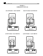
Страница 8: ...ead from your amplifier or receiver should be connected to one BLACK INPUT terminal HIGH EFFICIENCY LOW EFFICIENCY See Figure 3 page 9 VERY IMPORTANT NEVER CONNECT THE AMPLIFIER LEADS TO BOTH RED TERM...

Страница 9: ...IN USA TWEETER LEVEL EFFICIENCY AMPLIFIER _ _ one channel only is shown SATELLITE SPEAKER CONNECT AMPLIFIER TO ONLY ONE RED AND ONE BLACK TERMINAL see instructions HIGH HIGH LOW LOW MADE IN USA TWEETE...

Страница 10: ...ossible sound The second pair of terminals is provided to allow you to bi wire the S 1C The bi wiring technique is discussed below Sound quality can be affected by the type of speaker wire that you us...

Страница 11: ...TOUR SWITCH The MIDRANGE CONTOUR switch is the primary control for altering the tonal balance of your Satellites Its major effect is in the midrange but it does shift the balance over the entire audib...

Страница 12: ...requency level and distortion For example many recordings and film soundtracks have artificially boosted excessive high frequencies that will be clearly reproduced by the exacting and extended high fr...

Страница 13: ...should be connected to the upper set of terminals on the S 1C backplate labelled BI WIRE TWEETER INPUT The toggle switch located between both pairs of terminals must be set to the BI WIRE position In...

Страница 14: ...r ear with a slight time delay compared to the direct sound reaching your ear This time delay will blur the sonic imaging and interfere with transient performance The delay is very slight so instead o...

Страница 15: ...l sound However the vertical dispersion of the S 100B is not controlled to the degree of the S 1C so it is acceptable to place it with the tweeters in a horizontal line either above or below the 5 woo...

Страница 16: ...then just to the left or the right of the screen is next best If the television is not in the center of the room or not centered between the Left and Right speakers the proper location for the Center...

Страница 17: ...t the subwoofer to the front Left and Right channel amplifier outputs do not use the Center channel VERY IMPORTANT When the Subwoofer is connected to the Left and Right amplifier outputs and the contr...

Страница 18: ...hness and break up especially at high volume levels and turn down the volume when needed If you cannot get enough volume you may need to consider a higher powered amplifier If you have any questions a...

Страница 19: ...mnimounts varies according to production date Some S 90s have the inserts on the back baffle of the cabinet and other S 90s have the inserts on the bottom of the cabinet See page 20 for which bracket...

Страница 20: ...OmniMount Series 75 mounting bracket S 90 when threaded inserts are on the bottom of the S 90 USES OMNIMOUNT 75 WB Four threaded inserts are located on the bottom or top when the speaker is inverted o...

Отзывы: