2nd Edition, July 2015
1/59
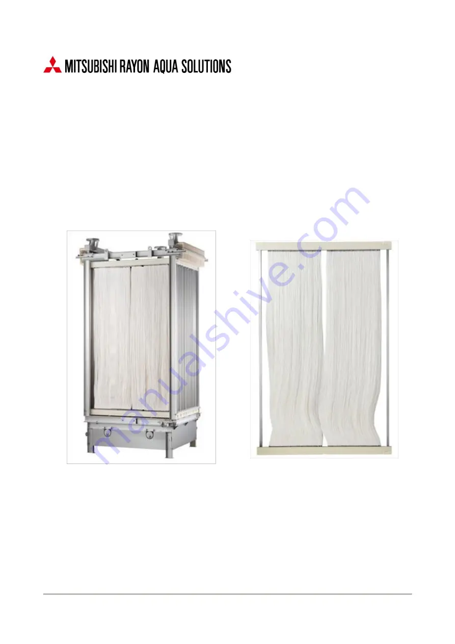
STERAPORE 5600 Series (FF)
Instruction Manual
Страница 1: ...2nd Edition July 2015 1 59 STERAPORE 5600 Series FF Instruction Manual...
Страница 2: ...operation and maintenance of the STERAPORE 5600 Series FF Please read this manual completely before using this product and use the product safely and appropriately Keep this manual in a safe place af...
Страница 3: ...MENT 28 4 2 ACTIVATED SLUDGE 30 4 3 SUPPLEMENTS 30 CHAPTER 5 TRANSPORT AND INSTALLATION 31 5 1 TRANSPORT AND INSTALLATION 31 5 2 PROCEDURES FOR LIFTING UP MODULES 38 CHAPTER 6 OPERATION 40 6 1 COMMISS...
Страница 4: ...atment at a hospital as an outpatient 3 Property damage refers to widespread damage to buildings household belongings livestock and or pets Prohibited actions and actions which must be performed are i...
Страница 5: ...on caused by aeration Use elements with due care to prevent tools pipes or other machines from touching the membrane Do not perform construction work that may damage modules especially membranes near...
Страница 6: ...ane pore diameter is possible Figure 1 1 shows a schematic diagram of conventional activated sludge processing and MBR Figure 1 1 Schematic Diagram of Conventional Activated Sludge Processing and MBR...
Страница 7: ...two types of MBR system Integrated MBR systems which place membrane modules in aeration tanks Separate MBR systems which place membrane modules in separate membrane tanks Figure 1 2 shows schematic di...
Страница 8: ...fers according to the raw water flow rate and flow rate fluctuations the treatment capacity of the membrane separation device etc Aeration tank There are two types of MBR system integrated MBR systems...
Страница 9: ...ter Return activated sludge pump RAS pump The RAS pump is required to adjust the sludge concentration of the reactor and membrane tanks When using recycled nitrification the pump also circulates nitri...
Страница 10: ...equipment blower pipe diffuser etc is suitable for all of these uses Place the inlet for raw water as far as possible from modules to prevent undecomposed raw water from coming into direct contact wit...
Страница 11: ...embrane tank to allow swirl flow to be evenly created See Table 1 1 for minimum water depth for each module CAUTION A failure to secure the minimum water depth will prevent stable operation Table 1 1...
Страница 12: ...ation operation As membrane surface scouring Figure 2 1 cannot be carried out while the pump is stopped if filtration continues the trans membrane pressure will rise quickly Install an automatic valve...
Страница 13: ...eeded perform chemical cleaning immediately The alarm and abnormal stop pressures may be set at values considered to be appropriate CAUTION Depending on how the permeate pump and pipes are installed a...
Страница 14: ...m 3 m 2 h or greater may result in damage to elements If the same blower is used for both biological processing and membrane scour aeration control the volume of membrane scouring air at the constant...
Страница 15: ...imilar accordingly to cover the time between the blower starting and the permeate pump starting Make sure that the diffuser cleaning operation is automatic As diffusers tend to clog if sludge is very...
Страница 16: ...on Manual 16 59 CAUTION When designing the piping make sure that tank water flowing backward through the diffuser does not flow into the blower while the blower is stopped When feeding clear water int...
Страница 17: ...s SDS CAUTION Monitor the suction pressure of the module and prevent the pressure from exceeding the set value the initial value of suction pressure 15 kPa trans membrane pressure index negative press...
Страница 18: ...low 0 4 m 3 m 2 d or less when treating domestic wastewater on a small scale Recovery cleaning Recovery cleaning which is performed every 3 months or when the suction pressure the trans membrane press...
Страница 19: ...wash the module with water again 4 For separate MBR systems the modules may also be left in the membrane tank to soak with the sludge in the tank being replaced with chemicals To clean elements 1 It i...
Страница 20: ...apter 3 Chemical Cleaning STERAPORE 5600 Series FF Instruction Manual 20 59 Figure 3 1 Diagram of a Module Immersed in a Washing tank Figure 3 2 Diagram of a Membrane Element Immersed in a Washing Tan...
Страница 21: ...tank See Figure 3 3 It is recommended to make the difference in water level 1 m or greater WARNING Mixing sodium hypochlorite NaClO and acid releases chlorine gas which is very dangerous Do not mix th...
Страница 22: ...e to rain or other reasons finish cleaning before it increases or postpone cleaning Residual Free Chlorine in Membrane Treated Water After Maintenance Cleaning Some of the NaClO used in maintenance cl...
Страница 23: ...elease air from the cleaning line by running the chemical and dilution water pumps while the permeate pump is running In a small modules if chemical solution is fed by using temporary tanks and hoses...
Страница 24: ...ter reducing it with sodium thiosulfate Dispose of acid wastewater after neutralizing it with sodium hydroxide If NaClO and acid are mixed poisonous chlorine gas is released which is very dangerous If...
Страница 25: ...calculations in 3 2 1 and select pumps and instruments so the amount of chemical solution can be adjusted This diagram shows a procedure in which undiluted chemical solution and dilution water are mi...
Страница 26: ...water for NaClO Design example Dilution water Tap water membrane treated water etc Tank capacity Must be greater than or equal to the amount required for a single cleaning cycle Supply method for dilu...
Страница 27: ...g and recovery cleaning are basically performed automatically it is recommended to incorporate these processes into a program in advance On the basis of the schematic diagram of chemical cleaning equi...
Страница 28: ...Sulfuric acid or caustic soda is generally used as a neutralizer Operate a pH meter and a chemical feeding pump together to control the amount of neutralizer added Grease and oil Grease and oil widel...
Страница 29: ...a substance that inhibits biological processing it must be removed Examples include cyanide compounds and heavy metals such as hexavalent chromium Examine in advance if the water contains any such sub...
Страница 30: ...tivated sludge is muddy when sludge volume is measured in accordance with the Gesuishikenhoho Japan Sewage Works Association or JIS B9944 Although SV30 is normally measured when measuring sludge volum...
Страница 31: ...place where small animals or insects may enter the products and take measures to prevent them from entering the products Excessive vibration can damage the products Avoid transporting the products on...
Страница 32: ...ckable elements 1 56E0040SA 10 2 060 1 330 470 1 3 140 0 186 0 5 20 2 060 1 330 790 2 2 280 0 341 0 3 2 SADF LTSUGIGU3 20 275 385 220 0 023 2 2 3 3 The above numbers are subject to change without noti...
Страница 33: ...Chapter 5 Transport and Installation STERAPORE 5600 Series FF Instruction Manual 33 59 Figure 5 5 Module diffuser part Packaging...
Страница 34: ...ushing pipes at the design flow rate Then inspect the devices and equipment before starting operation Perform cleaning and inspection similarly for raw water pumps permeate pumps blowers and pipes use...
Страница 35: ...pipe leaks cause mixing of suspended solids deterioration in the turbidity of treated water and poor suction Perform the test at a pressure of 100 kPa or greater Although it is preferable to perform t...
Страница 36: ...xcessive temperatures Never let them freeze 2 Open the packages Open the packages of both the membrane and diffuser parts of the modules Be careful not to damage the membrane modules when opening the...
Страница 37: ...dules is no more than 6 mm If the difference is higher than this diffusion between the modules will not be uniform CAUTION Take care as modified tanks may be sloped Make sure that diffusers in the sam...
Страница 38: ...60 degrees All modules have four or six lifting lugs for attaching lifting tools Select a crane or chain block a balance wire rope SUS chain hooks shackles etc by referring to values in Figure 5 8 an...
Страница 39: ...r 5 Transport and Installation STERAPORE 5600 Series FF Instruction Manual 39 59 Table 5 2 Estimated Length of the Balance and Lifting Height Figure 5 8 Schematic Drawing of a Membrane Module s Liftin...
Страница 40: ...er Commissioning Carry out stand alone commissioning for the devices below Stand alone commissioning of devices confirm that each device functions as stated in its specifications and record major data...
Страница 41: ...ing municipal wastewater Wastewater can refer to municipal wastewater and industrial wastewater MBR system operation must be managed in a manner specific to each individual facility In addition system...
Страница 42: ...Chapter 6 Operation STERAPORE 5600 Series FF Instruction Manual 42 59 Figure 6 1 Schematic Diagram of an Example MBR System Using Recycled Nitrification Processing...
Страница 43: ...ign flow rate is achieved Weekly or monthly change is small Smooth swirl and mixing with no unpleasant odor Small amount of sludge and scum generation Pump inspection Water level gauge inspection Mixe...
Страница 44: ...rease the air flow rate Decrease the air flow rate Filtration flow rate Calculated using the set value 0 2 to 0 8 m d At or above the set value At or below the set value Decrease the filtration amount...
Страница 45: ...Chapter 6 Operation STERAPORE 5600 Series FF Instruction Manual 45 59 Figure 6 2 Diagram of Operation Management Procedures...
Страница 46: ...nd create graphs from this data Always record the following requisite items and keep the record Take measurements at least once a week Inspection items concerning extra fine screens aerobic tanks and...
Страница 47: ...embrane flux at start up Reference value Design membrane flux Current MLSS concentration Design MLSS concentration Sludge input is calculated using the following formula Seeding Amount Q Q1 Q2 n n Q1...
Страница 48: ...g occurs Do not use silicon antifoaming agents as they cause membrane clogging pH decrease A pH decrease may occur due to progress in nitrification or a lack of denitrification Check the DO of the aer...
Страница 49: ...not mixed Failure of the submerged mixer Perform inspection and repair Aerobic tank membrane module Decline in filtration amount Failure of the permeate pump Perform inspection and repair Adjust to t...
Страница 50: ...f DO due to an increase in the MLSS concentration Adjust the ORP value so it is in the proper range Adjust the circulation pump flow rate Check the quality of raw water Decrease the amount of sludge e...
Страница 51: ...lements to dry out If elements dry out they must be rehydrophilized 1 Wash the element to remove any sludge adhered to it 2 Cut the hollow fiber requiring repair at around 30 to 50 mm from the potting...
Страница 52: ...odule from falling into the tank a cover and danger markings Be careful when working on a concrete floor or iron plate as they may be slippery Confirm that appropriate steps have been taken to prevent...
Страница 53: ...t with water Then perform chemical soak cleaning 2 After chemical soak cleaning fill a tank with tap water or any water of comparable quality and immerse the module in it Store the module in a cool da...
Страница 54: ...membrane and ultrafiltration membranes UF membrane are mainly used as separators MBR provides improved sewage treatment can be used to downsize and simplify treatment facilities and treated water can...
Страница 55: ...emical cleaning is performed either by washing the permeate side inner side of the membrane with a chemical solution in place cleaning in place CIP or by soaking the module or element directly in a ch...
Страница 56: ...ironment No guarantee is hereby provided 9 3 Chemical Resistance of the Product The chemical resistance of the product is shown in Table 9 2 Only use the product in MBR systems for organic wastewater...
Страница 57: ...iber membrane mm 1 65 Element dimensions D W H mm 30 1 250 2 000 Dry weight kg Approx 15 Connection mm 24 2 locations Upper element permeate header lateral Operating conditions Design filtration flow...
Страница 58: ...ge 80A Flange 80A Flange 80A Flange 80AFlange 2 Diffuser air Minimum aeration rate Nm 3 min 0 8 1 5 2 2 2 9 4 4 Maximum aeration rate Nm 3 min 1 7 3 1 4 5 5 9 9 0 Standard aeration rate Nm 3 min 1 5 2...
Страница 59: ...es FF Instruction Manual 2nd Edition July 2015 For inquiries please contact MITSUBISHI RAYON AQUA SOLUTIONS CO LTD Membrane Department Membrane Division 10F Gate City Ohsaki East Tower 1 11 2 Osaki Sh...