


267
PID control
4
(4) I/O signals and parameter setting
⋅
Turn ON the X14 signal to perform PID control. When this signal is OFF, PID action is not performed and normal
inverter operation is performed
(
when
Pr. 128
= "10, 11, 20, 21, 40, or 41"
).
⋅
Enter the set point across inverter terminals 2-5 or into
Pr. 133
and enter the measured value signal across inverter
terminals 4 and 5. At this time, set any of "20, 21, 120, 121" in
Pr. 128
.
⋅
When entering the externally calculated deviation signal, enter it across terminals 1 and 5. At this time, set any of
"10, 11, 110, 111" in
Pr. 128
.
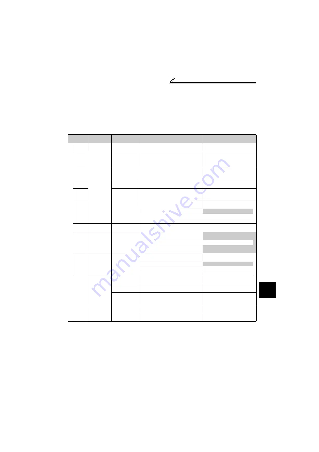
Input signals
Signal
Terminal
Used
Function
Description
Parameter Setting
In
p
ut
X14
Depending on
Pr. 178 to Pr.
189
PID control
selection
Turn ON X14 to perform PID control.
Set 14 in any of
Pr. 178 to Pr. 189
.
X64
PID forward/
reverse action
switchover
By turning ON X64, forward action can be
selected for PID reverse action (
Pr. 128
=
"10, 20, 110, 120"), and reverse action for
forward action (
Pr. 128
= "11, 21, 111, 121").
Set 64 in any of
Pr. 178 to Pr. 189
.
X72
PID integral value
reset
ON: Integral and differential values are
reset
OFF: Normal processing
Set 72 in any of
Pr. 178 to Pr. 189
.
X77
Pre-charge end
command
Turn ON X77 to end the pre-charge
operation and start PID control.
Set 77 in any of
Pr. 178 to Pr. 189
.
X78
Second pre-
charge end
command
Turn ON X78 while RT is ON to end the
pre-charge operation and start PID
control.
Set 78 in any of
Pr. 178 to Pr. 189
.
2
2
Set point input
Enter the set point for PID control.
Pr. 128
= "20, 21, 120, 121"
Pr. 133
= "9999"
0 to 5V ............... 0 to 100%
Pr. 73
= "1
, 3, 5, 11, 13, 15"
0 to 10V ............. 0 to 100%
Pr. 73
= "0, 2, 4, 10, 12, 14"
0 to 20mA .......... 0 to 100%
Pr. 73
= "6, 7, 16, 17"
PU
⎯
Set point input
Set the set value
(Pr. 133)
from the
operation panel or parameter unit.
Pr. 128
= "20, 21, 120, 121"
Pr. 133
= "0 to 100%"
1
1
Deviation signal
input
Input the deviation signal calculated
externally.
Pr. 128
= "10
, 11, 110, 111"
-5V to +5V ......... -100% to +100%
Pr. 73
= "2, 3, 5, 7, 12, 13, 15, 17"
-10V to +10V ..... -100% to +100%
Pr. 73
= "0, 1
, 4, 6, 10, 11, 14,
16"
4
4
Measured value
input
Input the signal from the detector
(measured value signal).
Pr. 128
= "20, 21, 40, 41, 120, 121,
140, 141"
4 to 20mA .......... 0 to 100%
Pr. 267
= "0"
0 to 5V ............... 0 to 100%
Pr. 267
= "1"
0 to 10V ............. 0 to 100%
Pr. 267
= "2"
Communi
-
cation
⎯
Deviation value
input
Input the deviation value from L
ON
W
ORKS
,
CC-Link, or BACnet communication.
Pr. 128
= "50, 51"
Set point input
Input the set point from L
ON
W
ORKS
, CC-
Link, or BACnet communication.
Pr. 128
= "40, 41, 140, 141"
Set value,
measured value
input
Input the set value and measured value
from L
ON
W
ORKS
, CC-Link, or BACnet
communication.
Pr. 128
= "60, 61"
PLC
⎯
Deviation value
input
Input the deviation value from PLC
function.
Pr. 128
= "70, 71, 90, 91"
Set value, measured
value input
Input the set value and measured value
from PLC function.
Pr. 128
= "80, 81, 100, 101"
*1
The shaded area indicates the parameter initial value.
*2
When
Pr. 128
= "40, 41, 50, 51, 60, 61, 140, 141" and the operation mode is not NET, input method is same as when
Pr. 128
= "10, 11, 20, 21"
respectively. Input from BACnet communication is available when the operation mode is NET,
Pr. 549
= "2" (BACnet), and RS-485 terminal
has the command source. Input from LonWorks or CC-Link communication is available when BACnet communication is inactive and the
operation mode is NET.
For the setting method via L
ON
W
ORKS
communication, refer to the L
ON
W
ORKS
communication option (FR-A7NL) instruction manual.
For the setting method via CC-Link communication, refer to the CC-Link communication option (FR-A7NC) instruction manual.
For the setting method via BACnet communication,
refer to page 249.
Содержание -NAFR-F720-00167-NA
Страница 22: ...12 MEMO ...
Страница 364: ...354 MEMO ...
Страница 378: ...368 MEMO ...
Страница 396: ...386 MEMO ...