background image

EXTERIOR – REAR SPOILER

51-5

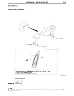
Rear Spoiler

Removal and Installation

Removal procedure

• Boot lid bumper
1. Cap
2. Rear spoiler

Double-sided tape: Generic products A: width 5 mm, thickness 0.8 mm, 
B: width 5 mm, thickness 1.2 mm
Primer: Sumitomo 3M 8107 PP parts primer

Remarks :
The removal and installation service points are the same as those for the air dam, bumper moulding, wing and door moulding
in the previous model.

A


A

Содержание Lancer Evolution VII

Страница 1: ...nges in the shape of the front bumper and addition of new components Addition of components due to changes in rear spoiler shape and change in the positioning of double sided adhesive tape Change in the shape of three diamond mark EVOLUTION mark and LANCER mark and change in the positioning of EVOLUTION mark and LANCER mark General 1 Front bumper 2 Adhesives 2 Front bumper 2 Rear spoiler 4 Adhesiv...

Страница 2: ...2 Centre under cover 3 Under cover centre bracket 4 Front under cover Splash shield installation clip Water spray hose connection see Chapter 15 5 Front bumper assembly Section A A clip Section B B clip clip Section C C Application Brand Three Diamond Mark Double sided tape Generic product width 20 mm thickness 0 8 mm fender ...

Страница 3: ...EXTERIOR FRONT BUMPER 51 3 Double sided tape Generic tape Width 20 mm Thickness 0 8 mm Disassembly and Reassembly Clip Clip Section A A Section B B ...

Страница 4: ...ssembly 16 Front bumper upper reinforcement assembly 17 Front bumper face Disassembly service points A Removal of front bumper side plate Use the same procedure as that for removal of front bumper rivets in previous model Reassembly service points A Installation of front bumper side plate Use the same procedure as that for installation of front bumper rivets in previous model Rear Spoiler Adhesive...

Страница 5: ... 2 Rear spoiler Double sided tape Generic products A width 5 mm thickness 0 8 mm B width 5 mm thickness 1 2 mm Primer Sumitomo 3M 8107 PP parts primer Remarks The removal and installation service points are the same as those for the air dam bumper moulding wing and door moulding in the previous model A A ...

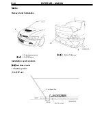
Страница 6: ...51 6 Marks Removal and Installation 1 Three diamond mark A 2 LANCER mark A 3 EVOLUTION mark Installation service points A Installation of marks 1 Installation position 2 LANCER mark Boot lid end line Boot lid end line ...

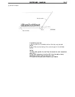
Страница 7: ...ve backing of the mark and apply it to the installation position Caution 1 Perform this operation in a dust free environment at a room temperature of 20 38 C 2 If the room temperature is less than 20 C then the mark and body installation position must be heated to 20 30 C 3 The mark must be pressed to eliminate any air bubbles Boot lid end line Boot lid end line ...

Отзывы: