Mitsubishi L02CPU Скачать руководство пользователя страница 185

183

CHAPTER 4 DISPLAY UNIT FUNCTIONS

4


CHAPTER 4

DISPLAY UNIT FUNCTIONS

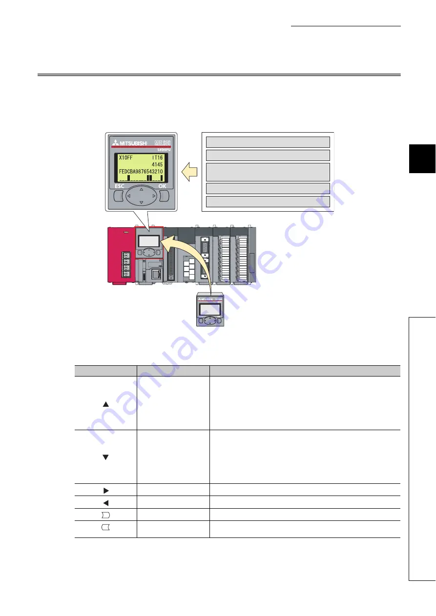
A display unit is an LCD attachable to the CPU module. Using a display unit allows checking system status and 
changing system setting values without software packages.
If an error occurs, the error cause can be determined by displaying the error information.

(1) Description of the buttons

Unless otherwise specified, buttons on a display unit operate as follows.

Type

Name

Description

Up arrow button

Moves the cursor up, scrolls the screen up, and increases values. In the following 
screens, pressing a device longer will increase a bit device value in increments of 
10 bits (decimal notation) or 16 bits (hexadecimal notation), and will increase a 
word device value in increments of 10 words (decimal notation) or 16 words 
(hexadecimal notation).

• Device monitor/test
• Buffer memory monitor/test

Down arrow button

Moves the cursor down, scrolls the screen down, and decreases values. In the 
following screens, pressing a device longer will increase a bit device value in 
increments of 10 bits (decimal notation) or 16 bits (hexadecimal notation), and will 
increase a word device value in increments of 10 words (decimal notation) or 16 
words (hexadecimal notation).

• Device monitor/test
• Buffer memory monitor/test

Right arrow button

Moves the cursor forward and switches screens.

Left arrow button

Moves the cursor back and switches screens.

OK button

Switches screens, executes functions, and accepts selection.

ESC button

Returns the display to the previously displayed screen or the initial screen for each 
function.

Device monitor/test

Forced on/off

Checking/changing the I/O status and setting

values of intelligent function module

Error information/log display

Scan time display

OK

ESC

Содержание L02CPU

Страница 1: ......

Страница 2: ......

Страница 3: ...re to do so may result in an accident due to an incorrect output or malfunction 1 Emergency stop circuits protection circuits and protective interlock circuits for conflicting operations such as forward reverse rotations or upper lower limit positioning must be configured external to the programmable controller 2 Machine OPR Original Point Return of the positioning function is controlled by two ki...

Страница 4: ...y is turned on first an accident may occur due to an incorrect output or malfunction Configure a circuit so that the external power supply is turned off first and then the programmable controller If the programmable controller is turned off first an accident may occur due to an incorrect output or malfunction For the operating status of each station after a communication failure refer to relevant ...

Страница 5: ...in all phases before mounting or removing a module Failure to do so may result in electric shock or cause the module to fail or malfunction CAUTION Use the programmable controller in an environment that meets the general specifications in the MELSEC L CPU Module User s Manual Hardware Design Maintenance and Inspection Failure to do so may result in electric shock fire malfunction or damage to or d...

Страница 6: ...l device Tighten the terminal block screw within the specified torque range Undertightening can cause short circuit fire or malfunction Overtightening can damage the screw and or module resulting in drop short circuit fire or malfunction When disconnecting the cable from the module do not pull the cable by the cable part For the cable with connector hold the connector part of the cable For the cab...

Страница 7: ...e malfunction Shut off the external power supply for the system in all phases before mounting or removing a module Failure to do so may cause the module to fail or malfunction Tighten the terminal block screw within the specified torque range Undertightening can cause drop of the component or wire short circuit or malfunction Overtightening can damage the screw and or module resulting in drop shor...

Страница 8: ...rding to the local regulations For details on battery regulations in EU member states refer to the MELSEC L CPU Module User s Manual Hardware Design Maintenance and Inspection CAUTION When transporting lithium batteries follow the transportation regulations For details on the regulated models refer to the MELSEC L CPU Module User s Manual Hardware Design Maintenance and Inspection ...

Страница 9: ... the PRODUCT in Nuclear Power Plants and any other power plants operated by Power companies and or any other cases in which the public could be affected if any problem or fault occurs in the PRODUCT Railway companies or Public service purposes and or any other cases in which establishment of a special quality assurance system is required by the Purchaser or End User Aircraft or Aerospace Medical a...

Страница 10: ...oduct correctly When applying the program examples introduced in this manual to the actual system ensure the applicability and confirm that it will not cause system control problems Relevant CPU modules L02CPU and L26CPU BT Remark This manual does not describe the details of the instructions error codes special relay SM and special register SD For the instructions refer to the following QCPU LCPU ...

Страница 11: ... manual number model code Description QCPU LCPU Programming Manual Common Instruction SH 080809ENG 13JW10 Detailed description and usage of instructions used in programs MELSEC Q L QnA Programming Manual SFC SH 080041 13JF60 System configuration specifications functions programming and error codes for SFC MELSAP3 programs MELSEC Q L Programming Manual MELSAP L SH 080076 13JF61 System configuration...

Страница 12: ...MELSEC communication protocol MC protocol that is used for data communication between a target device and a CPU module MELSEC L CC Link System Master Local Module User s Manual SH 080895ENG 13JZ41 Settings specifications handling data communication methods and troubleshooting of the built in CC Link function of the CPU module or the CC Link system master local module MELSEC L Analog Digital Conver...

Страница 13: ...11 Memo ...

Страница 14: ... 2 APPLICATION OF PROGRAMMING 30 2 1 Memories and Files 30 2 1 1 Memories 30 2 1 2 Parameter valid drive 33 2 1 3 Files 34 2 2 I O Number 39 2 2 1 Concept of I O number assignment 39 2 2 2 I O number assignment 40 2 3 Scan Time Structure 42 2 3 1 Initial processing 42 2 3 2 Refresh processing of input output modules or intelligent function modules 43 2 3 3 Program operation 43 2 3 4 END Processing...

Страница 15: ...passwords 97 3 11 2 Password authentication 102 3 12 Remote Password 104 3 13 Remote Operation 106 3 13 1 Remote RUN STOP 106 3 13 2 Remote PAUSE 108 3 13 3 Remote RESET 110 3 13 4 Remote Latch Clear 111 3 14 Scan Time Measurement 112 3 15 Program List Monitor 114 3 16 Interrupt Program List Monitor 115 3 17 Local Device Monitor Test 116 3 18 External Input Output Forced On Off 118 3 19 Executiona...

Страница 16: ...unction 182 CHAPTER 4 DISPLAY UNIT FUNCTIONS 183 4 1 Function List 187 4 2 CPU Monitor Test 188 4 2 1 Device monitor test 188 4 2 2 Device clear 196 4 2 3 Forced on off 199 4 2 4 Scan time monitor 202 4 2 5 Built in I O function monitor 203 4 2 6 Error display clear 207 4 3 CPU Settings 211 4 3 1 Clock setting 211 4 4 Module Monitor Test 213 4 4 1 Buffer memory monitor test 213 4 5 Module Settings...

Страница 17: ...ter Standard Device Register Z 255 5 5 1 Index Register Z 255 5 5 2 Standard device register Z 256 5 5 3 Saving and restoration of the index register 257 5 6 File Register R ZR 259 5 7 Extended Data Register D and Extended Link Register W 264 5 8 Nesting N 269 5 9 Pointer P 270 5 9 1 Local pointer 271 5 9 2 Common pointer 272 5 10 Interrupt Pointer I 273 5 11 Other Devices 274 5 11 1 SFC block dev...

Страница 18: ... Scan Time 304 Appendix 2 2 Factors that Increase the Scan Time 309 Appendix 3 Data Used in the CPU Module 312 Appendix 4 Character Codes Available in the Display Unit 314 Appendix 5 Differences Between LCPU and QnUCPU 326 Appendix 5 1 Specification Comparison 326 Appendix 5 2 Precautions for Utilizing Programs 327 Appendix 6 Precautions for Using GX Works2 328 Appendix 7 Precautions for Using GX ...

Страница 19: ... for items in the menu bar and the project window shows operating procedures shows reference manuals shows notes that requires attention shows mouse operations 1 shows reference pages shows setting or operating examples Ex shows useful information A window selected in the view selection area is displayed View selection area Online Write to PLC Select Online on the menu bar and then select Write to...

Страница 20: ...6BAT and Q7BAT are available SD memory card Secure Digital Memory Card which is a flash memory device The L1MEM 2GBSD and L1MEM 4GBSD are available LCPU Another term for the MELSEC L series CPU module QnUCPU Another term for the MELSEC Q series Universal model QCPU Programming tool Generic term for GX Works2 and GX Developer GX Works2 Product name of the software package for the MELSEC programmabl...

Страница 21: ...19 PART 1 PROGRAMMI NG In this part fundamental knowledge of programming is described CHAPETR 1 BASIC PROCEDURE FOR PROGRAMMING 20 CHAPETR 2 APPLICATION OF PROGRAMMING 30 ...

Страница 22: ...onverting programs Convert created programs into ones that can be processed by the CPU module Writing projects Debug the programs using the monitoring function Checking operations End Write the projects to the CPU module For the first use of the CPU module format the used memory beforehand Saving projects Page 22 Section 1 2 Page 29 Section 1 7 Page 23 Section 1 3 Page 24 Section 1 4 Page 25 Secti...

Страница 23: ...on Example The following system configuration is used for description throughout this chapter 1 Wiring of the power supply module and I O modules are omitted in this illustration CPU module L02CPU Power supply module L61P GX Works2 Input module LX42C4 Output module LY42NT1P END cover L6EC USB connection ...

Страница 24: ... Select a type of project to create In this chapter Simple Project is selected Use Label Select this checkbox when using a label for programming In this chapter this is not selected PLC Series Select a series of the CPU module to use in the project In this chapter LCPU is selected PLC Type Select a type of the CPU module CPU module model to use in the project In this chapter L02 is selected Langua...

Страница 25: ... a program Page 226 CHAPTER 5 2 Concept of I O numbers I O numbers are automatically assigned Users can also assign I O numbers according to their purposes Page 39 Section 2 2 3 Program configuration A main routing program subroutine program Page 43 Section 2 3 3 and interrupt program Page 53 Section 2 7 can be included in a program Device Constant Power supply module CPU module Input module Outpu...

Страница 26: ...ladder Compile Build The program has been converted In the next procedure write the program to a CPU module To use a label the program must be compiled GX Works2 Version1 Operating Manual Common After modifying a program it must be compiled 1 To enter X10 type X10 at the original cursor position and select the contact shown in the left figure 2 To enter Y20 type Y20 and select the coil shown in th...

Страница 27: ... module Note that when the program is new the memory Page 30 Section 2 1 1 is formatted so that a program can be written to it 1 5 1 Formatting a memory To format a memory open the Format PLC Memory dialog box In this chapter a program memory is formatted so that a program can be written to it Online PLC Memory Operation Format PLC Memory To check the capacity of the memory after formatting open t...

Страница 28: ...e project has been written In the next procedure execute the program Note that parameter setting is required to operate CPU modules In this chapter the procedure for parameter setting is not introduced since default values are used Page 284 Appendix 1 1 Select the program memory 2 Selecting this will automatically select the parameter and program checkboxes ...

Страница 29: ... In the next procedure run the CPU module To run use the switch on the CPU module When the RUN LED is lit green the program is being executed successfully By remote operation CPU modules can be operated without using switches Page 106 Section 3 13 1 Before resetting the CPU module check the current LED status 2 Move the switch on the front of the CPU module to the RESET position One second or long...

Страница 30: ...e conducting they are shown in blue Alternatively device states can be checked through a display unit Page 188 Section 4 2 1 Debug can be performed by forcibly turn on or off devices in the Modify Value dialog box Debug Modify Value For details on current value changing refer to the following GX Works2 Version1 Operating Manual Common If a program is edited during debugging the program can be writ...

Страница 31: ...t titles Item Description Save Folder Path Enter the storage destination folder drive or path of the workspace Folders can be browsed for selection by clicking the button Workspace Project List Select a workspace Double click Workspace to display a project list Workspace Name Enter a name for the workspace Project Name Enter a name for the project Title 1 Enter a title for the project ...

Страница 32: ...ssing at reset 1 The program cache memory is used for program operations b Writing to the program memory When a program is written to the program memory it is temporarily written to the program cache memory and then automatically transferred back to the program memory While the CPU module is in the RUN status automatic data transfer to the program memory can be disabled by setting Page 138 Section...

Страница 33: ...nd module error collection files 3 Standard ROM This memory stores data such as device comments and PLC user data 4 SD memory card This memory stores programs and parameters To execute a program stored in the SD memory card perform a boot operation Page 71 Section 2 9 An SD card memory is required when using the data logging function 5 Memory capacity The following table shows the memory capacity ...

Страница 34: ...Program Memory Standard RAM Standard ROM SD memory card File name and extension any given name for Remarks Drive 0 Drive 3 Drive 4 Drive 2 Parameter PARAM QPA One file per drive Intelligent function module parameters 1 IPARAM QPA One data per drive Program QPG Device comment QCD Initial device value QDI File register 2 QDR Local device 2 QDL One file per module Sampling trace 2 QTD PLC user data C...

Страница 35: ...meters stored in the drive When the CPU module is powered off and then on When the CPU module is reset 2 Precautions Note that if the parameters are written while the CPU module is in operation the timing that the parameters take effect varies a To write a parameter to the drive other than the one in operation The CPU module keeps operating according to the current parameters When the CPU module i...

Страница 36: ...haracters File name Create with uppercase characters only Extension It is automatically appended according to the specified file type The following cannot be used as a file name since they are the reserved words of Microsoft Windows COM1 to COM9 PRN LPT1 to LPT9 NULL AUX CLOCK and CON When using characters recognition of uppercase and lowercase differs depending on the memory Program memory standa...

Страница 37: ...struction For the forced disablement of SD card refer to the following MELSEC L CPU Module User s Manual Hardware Design Maintenance and Inspection b Simultaneous writing to the same file from multiple programming tools While a file is being written accessing the file from another programming tool is not allowed Also while a file is being accessed writing data to the file from another programming ...

Страница 38: ...ial device value 66 44 number of settings of the initial device value 2 total number of device points set to the initial device value 72 8 File register 2 number of device points Local device 70 6 set device type 2 total number of M and V points 16 number of D and Z points 18 total number of T ST and C points 16 number of programs where local devices are used M V D T ST and C indicate the followin...

Страница 39: ...et by default Execution program This area stores the created program Reserved area for online change This area is used when the number of steps is increased after writing data in the RUN status Default 500 steps 2000 bytes After the online change is complete remaining number of steps for this area is displayed The setting value can be changed in the Online Data Operation dialog box It can be chang...

Страница 40: ...1 step only the amount equal to the program size is occupied 525 500 1025 steps 4100 bytes Calculation of parameter file size Since the parameter file capacity is 2936 bytes it occupies 734 steps 2936 bytes in the program memory Result Program size parameter file capacity 1025 734 1759 steps 7036 bytes Memory capacity can also be calculated from a programming tool Tool Confirm Memory Size For calc...

Страница 41: ...rs used in the actual system differ from those in the program the I O numbers of each module can be changed to the ones in the program If any of the I O modules whose number of I O points are other than 16 fails without I O assignment setting the I O numbers assigned following to the failed module may change leading to a malfunction For this reason making the I O assignment setting is recommended ...

Страница 42: ...arameter I O Assignment In the I O Assignment tab the following settings are also available Response time from I O I O Response Time Page 94 Section 3 8 CPU module operation upon an error Page 95 Section 3 9 CPU module operation upon hardware failure of an intelligent function module Page 96 Section 3 10 Switch setting of intelligent function modules ...

Страница 43: ... input module is connected the second half 16 points of the 32 point input module are invalid If the preset number of I O points exceeds those of connected I O modules the exceeded number of points will not be used Set the last I O number within the I O point range Failure to do so causes SP UNIT LAY ERR c Start XY setting Note that in the following two cases the start XY setting may be duplicated...

Страница 44: ...he switch is set from STOP to RUN the RUN LED will flash then back to STOP and to RUN again Note that the PLS P instruction instruction for pulse conversion may not be executed properly with the above operation This is because the previous information may not be inherited depending on the program changes Initial processing item CPU module status Powered on Reset Changed from STOP to RUN 1 The I O ...

Страница 45: ...es its operation from the step 0 to the END or FEND instruction This program is executed from the step 0 for every scan A main routine program can be divided to main routine and subroutine programs A subroutine program is from a pointer P to the RET instruction and is created between the FEND and END instructions This program is executed only when it is called by a subroutine program call instruct...

Страница 46: ...esting Page 269 Section 5 8 Using an interrupt pointer in a subroutine program changes the program to an interrupt program Page 53 Section 2 7 2 3 4 END Processing END processing includes the following Auto refresh with intelligent function module Intelligent function module dedicated instruction processing Device data latch processing Service processing Watchdog time reset Self diagnostics proces...

Страница 47: ...f operations performed for one scan after entering the RUN status b Processing time required before operations The processing time required for the CPU module to start program operations after its operating status is changed from STOP to RUN varies depending on the system configuration and or parameter settings Normally it takes one to three seconds 2 Operation processing in the STOP status Stop s...

Страница 48: ... RUN STOP status CPU module operation processing Program operation processing External output Device memory M L S T C D Y RUN STOP The CPU module executes the program until the END instruction and stops The CPU module saves the output Y status immediately before its status is changed to STOP and turns off all the outputs The CPU module holds the device memory status immediately before its status i...

Страница 49: ...rt is specified for the SFC program data in the system is saved The CPU module restarts its operation processing Even if operation processing is suspended due to a momentary power failure the CPU module continues the measurement of the watchdog timer WDT When the WDT setting of PLC parameter is 200ms and the scan time is 190ms if a momentary power failure occurs for 15ms WDT ERROR occurs 2 When a ...

Страница 50: ... Outline of the processing The following describes the details of the refresh processing a Input Before starting a program operation the ON OFF data in the general purpose module and input module are collectively loaded to the General purpose input input module access area of the CPU module When a program is executed the ON OFF data in the input X device memory are used for operation b Output The ...

Страница 51: ... tool input area and Remote input refresh area is executed and then the data are stored in the input X device memory Output refresh Before program operation data in the output Y device memory 2 are collectively output to the output module Execution of an input contact instruction Input data in the input X device memory are read out 3 and the program is executed Execution of an output contact instr...

Страница 52: ... at the earliest timing Y5E turns on at the slowest timing A program that turns on the output Y5E when the input X5 is turned on Delay time minimum 1 scan OFF ON 0 END END 0 0 Input refresh 56 External contact OFF ON X5 OFF ON Y5E OFF ON External load CPU module devices Output refresh Delay time maximum 1 scan OFF ON 0 END END 0 0 Input refresh 56 External contact OFF ON X5 OFF ON Y5E OFF ON Exter...

Страница 53: ...he OR processing is performed between the input information of the input module 1 and the input data of the programming tool 2 or general purpose input 3 The result is stored in the input X device memory and is used as input data 4 to execute the program Execution of an output contact instruction Output data in the output Y device memory are read out 5 and the program is executed Execution of the ...

Страница 54: ...DY5E turns on at the earliest timing DY5E turns on at the slowest timing A program that turns on the output Y5E when the input X5 is turned on Delay time OFF ON 0 55 56 External contact OFF ON OFF ON DX5 External contact DY5E External load CPU module devices OFF ON 0 55 56 External contact OFF ON OFF ON DX5 External contact DY5E External load CPU module devices Delay time maximum 1 scan END 0 55 5...

Страница 55: ...am of the interrupt pointer number corresponding to that factor is executed Interrupt program are executed only after the corresponding interrupt factor occurs Main routine program Interrupt program I0 Interrupt program I29 Interrupt pointer Indicates the end of the main routine program Main routine program Interrupt program I0 Interrupt program I29 An interrupt factor for I0 occurred An interrupt...

Страница 56: ...n interrupt program a PLS and PLF instructions The PLS and PLF instructions perform off processing in the next scan of which the instruction is executed Therefore the device which is turned on by the instruction remains on until the same instruction is reexecuted b EI and DI instructions Do not execute the EI or DI instruction during interrupt program execution c Timer T and counter C Do not use t...

Страница 57: ...type programs are stored only once Note that all interrupt factors occurred are discarded if they are masked by the IMASK instruction b When an interrupt factor occurs in the STOP or PAUSE status The CPU module executes the interrupt program as soon as the interrupt program execution status is enabled after the CPU module status is changed to RUN Main routine program Interrupt program Interrupt fa...

Страница 58: ...all the interrupt programs corresponding to interrupt factors are executed after completion of current interrupt program execution e When an interrupt factor occurs during END processing When the constant scan function is used and an interrupt factor occurs during the waiting time in END processing an interrupt program corresponding to the interrupt factor is executed 4 Processing at program execu...

Страница 59: ...o prevent device data inconsistency Do not directly specify the device where the data are written by the interrupt program in the main routine program Use the data in another device by moving the data with the transfer instruction Disable interrupts with the DI instruction if instructions that may cause inconvenience for the main routine program are used Note that interrupts do not occur during ac...

Страница 60: ...rogram is executed once in every scan starting in the next scan of which the initial execution type program is executed and later Page 62 Section 2 8 2 Wait standby type program This program is executed only when requested Page 63 Section 2 8 3 Fixed Scan fixed scan execution type program This program is executed at time intervals specified in Fixed scan interval and In Unit Fixed scan interval En...

Страница 61: ...o RUN Use an appropriate type of program as required Power on or STOP RUN Initial execution type program Fixed scan execution type program Scan execution type program Standby type program END processing Executed once when the CPU module is powered on or switched from STOP to RUN Executed at specified intervals Program execution sequence Program execution when a subroutine program or interrupt prog...

Страница 62: ...med In the next scan and later scan execution type programs are executed Creating an initial execution type program Program A Program B Control by one program Processing performed once Processing performed in every scan Initial execution type program Scan execution type program One program is divided into an initial execution type program and scan execution type program Power on or STOP RUN Initia...

Страница 63: ...ed scan execution type program is executed before completion of the initial execution type program execution the execution time of the executed program will be added to the initial scan time When an interrupt program of fixed scan execution type program is executed before completion of the initial execution type program execution the execution time of the executed program will be added to the init...

Страница 64: ...he time required for completing all the scan execution type program execution If an interrupt program or fixed scan execution type program is executed execution time of the executed program will be added to the scan time 1st scan 2nd scan 3rd scan 4th scan STOP RUN Power on RUN END processing Initial execution type program Scan execution type program A Scan execution type program C Scan execution ...

Страница 65: ...rogram Program type change Standby type program is used to create and store programs available in all systems Only required programs will be executed For example a program preset as a standby Wait type program in the PLC Parameter dialog box can be changed to a scan execution type program and executed in the program 1 Execution method Execute standby type programs in either of the following method...

Страница 66: ...PU module re executes the program that called a program in the standby type program Use common pointers Page 270 Section 5 9 If local pointers are used subroutine programs in a standby type program cannot be executed from any other program Use a common pointer Main routine program Program A Program B standby type program P100 RET I0 IRET END processing CALL P100 instruction execution END processin...

Страница 67: ...ll not be changed in the middle of program execution If different types are set to the same program in the same scan the program will be changed to the type specified by the last instruction executed 2 Restrictions on creating a execution type program Unavailable devices depend on the program type subroutine program or interrupt program or the execution type changed by an instruction The PSCAN ins...

Страница 68: ...ruction For the restrictions on programming refer to Page 54 Section 2 7 2 The restrictions on programming are the same as those for interrupt programs To execute a fixed scan execution type program execute the EI instruction in the initial execution type program or scan execution type program to enable interrupts Fixed scan interval END processing Scan execution type program Fixed scan execution ...

Страница 69: ... program I28 to I31 reach the specified time at the same timing the interrupt program will be given priority c When the execution condition is established during END processing When the execution condition is established during the waiting time of the constant scan execution or the END instruction a fixed scan execution type program is executed 2 Processing at program execution type change For how...

Страница 70: ...llowing shows an example of the increase in execution time of a fixed scan execution type program With the settings above the condition 1 will be 0 5ms 5ms The execution time of a fixed scan execution type program whose execution interval is set to 10ms increases 100ms 5 0 5 10 100 at the most Highest common factor of fixed scan execution interval 1 Interrupt disabled time Condition 1 Fixed scan e...

Страница 71: ...the standby type Turns off outputs in the next scan Changes to the standby type in two scans later Initial execution type Changes to the scan execution type Changes to the standby type Turns off outputs in the next scan Changes to the standby type in two scans later Standby type Changes to the scan execution type Remains unchanged No processing Fixed scan execution type Changes to the scan executi...

Страница 72: ...F GHI JKL When M0 turns on the program ABC is changed from a standby type to a scan execution type program When M1 turns on the program ABC is changed from a scan execution type to a standby type program Control program The PSCAN instruction changes the program ABC to a scan execution type program The PSTOP instruction changes the program ABC to a standby type program Standby type program Standby ...

Страница 73: ...ory when the CPU module is powered off and then on or the CPU module is reset a Boot operation procedure 1 Create a program 2 Configure the setting for a boot operation Specify the file name and transfer destination to boot Project window Parameter PLC Parameter Boot File 3 Insert an SD memory card 4 Write the setting to the SD memory card parameters and the files set in the Boot File tab Reset th...

Страница 74: ...Set the maximum number of settable boot files in the Boot File tab of the PLC Parameter dialog box so that it is the same with the number of files storable to the program memory However the number of boot files is reduced by one when a heading is set or the parameters set in the Boot File tab of the PLC Parameter dialog box and stored in the SD memory card is booted The size unit of a file stored ...

Страница 75: ...e execution status of an operation in a sequence program step is referred to as signal flow 2 ST A text language such as C language and is preferred by computing engineers 3 SFC A graphical programming language where the execution order and conditions are clearly defined for the program 4 Structured ladder A graphical programming language that uses contacts and coils Remark For the projects that s...

Страница 76: ...lligent function module parameters Open the New Module dialog box Project window Intelligent function module Right click New Module Upon completion of the setting above parameters for the intelligent function module appear in the Project window To set the intelligent module parameters refer to the following Manual for the intelligent function module used Item Description Module Selection Module Ty...

Страница 77: ...ated instruction This instruction enables easy programming for the use of functions of the intelligent function module Serial communication module dedicated instruction OUTPUT instruction The OUTPUT instruction allows communications with external device by nonprocedural protocol regardless of the buffer memory address of the serial communication module a Processing of the intelligent function modu...

Страница 78: ...76 Memo ...

Страница 79: ...77 PART 2 FUNCTIONS In this part the functions of the CPU module and display unit are described CHAPETR 3 CPU MODULE FUNCTIONS 78 CHAPETR 4 DISPLAY UNIT FUNCTIONS 183 ...

Страница 80: ...itches Page 106 Section 3 13 1 Remote PAUSE Changes the CPU module status to PAUSE without using switches Outputs Y are held Page 108 Section 3 13 2 Remote RESET Resets the CPU module when it is in the STOP status without using switches Page 110 Section 3 13 3 Remote latch clear Clears latch data of the CPU module when the module is in the STOP status without using switches Page 111 Section 3 13 4...

Страница 81: ...al input devices Interrupt input function Executes an interrupt program using a built in external input or output signal as a trigger Pulse catch function Catches pulse signals with the ON time shorter than the scan time that the general purpose input function cannot catch Positioning function Controls a drive unit by outputting pulses from an external I O connector High speed counter function Cou...

Страница 82: ...le programs with constant scan setting 10ms 2 Constant scan time setting The setting range is from 0 5 to 2000ms in increments of 0 5ms When not using the constant scan function leave the setting box blank Project window Parameter PLC Parameter PLC RAS The constant scan accuracy is 0 01ms However constant scan time may increase when an interrupt program or a fixed scan execution type program is be...

Страница 83: ... time is longer than the WDT setting time the CPU module detects WDT ERROR In this case the program execution is stopped 3 Waiting time from when END processing is executed until next scan starts When an interrupt factor occurs during waiting time either of an interrupt program or fixed scan execution type program is executed When a service processing parameter is set a communication service proce...

Страница 84: ...ecuted within the setting value of watchdog timer When the watchdog timer times up WDT ERROR is detected and the following status occurs The CPU module turns off all outputs The RUN LED turns off and the ERR LED starts flashing SM1 turns on and the error codes 5000 and 5001 are stored in SD0 The watchdog timer can be reset by executing the WDT instruction in a program To avoid the time up of watch...

Страница 85: ...t change regardless of the latch 1 Devices that can be latched Set the device to latch among the following By default only the latch relay is allowed to be latched When the battery life prolonging function is set the latch function is disabled Page 166 Section 3 30 2 Latch range setting Set the following Project Window Parameter PLC Parameter Device Latch clear is enabled Latch 1 Start End The lat...

Страница 86: ...ONLINE Remote Operation Latch Clear Note that any of the following operation is required to clear the latch data and file registers that are set as the latch clear disabled data Latch 2 Start End Clear from the display unit Page 196 Section 4 2 2 Reset with the RST instruction Transfer K0 with the MOV or FMOV instruction MELSEC Q L Programming Manual Common Instruction Select Clear Device s whole ...

Страница 87: ...set or the CPU module status is switched from STOP to RUN 2 Devices that can be used 1 The following shows devices that can be used for initial device value 1 The initial device value setting has a priority over the latch setting 2 To use an intelligent function module select Module Synchronization because the initial device value may not be correctly set to the target module Page 284 Appendix 1 C...

Страница 88: ...ject Window Parameter PLC Parameter PLC File 2 Specify a name to store initial device values Project Window Device Initial Value Right click Add New Data 3 Clicking the button on the dialog box above opens the dialog box shown on the left Enter the range for initial device values To the next page ...

Страница 89: ... from STOP to RUN Therefore they cannot be used for the data that are to be changed in a program after being set at CPU module power on from off Use an instruction such as the MOV instruction in the main routine program so that the initial device values are set to the specified devices For the intelligent function module use the TO instruction to write data to the buffer memory 4 Configure the dev...

Страница 90: ...ncrease in the scan time and decrease in the service processing time 3 For the following functions scan time will be increased longer than the specified time during service processing even if the service processing time specification is set Online change Change T C setting Local device monitor Program memory backup Writing to reading from the file register or the buffer memory of an intelligent fu...

Страница 91: ...ce processing exists END processing speeds up by the amount of request processing time The CPU module does not wait for requests Program execution END processing Request 1 Program execution END processing Request 2 1 Program execution END processing Request 3 Peripheral Request 2 2 1ms 1ms 1 2ms The service processing time depends on the scan time program execution time When time required for proc...

Страница 92: ...ion END processing Request 2 Request 2 Request 3 1ms Request 3 Request 4 Multiple requests are processed until the processing time exceeds the set service processing time 1ms When the service processing time is exceeded the service processing is suspended and the remaining requests are processed at the END processing in the next scan The increases of the scan time remain constant even though quall...

Страница 93: ...time If no request data for service processing exists END processing speeds up by the amount of request processing time The CPU module does not wait for requests Program execution END processing Request 1 Program execution END processing Request 2 Program execution END processing Request 3 Peripheral Regardless of request data size one request is processed at one END processing Even if the program...

Страница 94: ...rformed Therefore when the waiting time is less than 0 2ms the constant scan time may be exceeded Program execution Waiting time END processing Program execution END processing Peripheral Request 1 Request 2 Request 3 Request 4 Waiting time The service processing is performed during waiting time Constant scan Constant scan Request 1 Request 2 Request 3 Request 4 Request 5 Program execution END pro...

Страница 95: ...STOP The CPU module outputs the output Y status immediately before the CPU module is changed to the STOP status and then performs program operations When the output Y status is forcibly turned on while the CPU module is in the STOP status the CPU module outputs the previous output Y status The on status is not held if the output Y status before the CPU module is changed to STOP status is off b Whe...

Страница 96: ...al Built In I O Function 1 Setting procedure 1 Select Input under Type in the I O Assignment tab and click the button Project Window Parameter PLC Parameter I O Assignment 2 Select any of the following values for I O Response Time Default 10ms 1ms 5ms 10ms 20ms 70ms The shorter the input response time is the more the CPU module is susceptible to noise Consider the operating environment when settin...

Страница 97: ...dules when a stop error occurs in the CPU module For the error time output mode setting by the built in I O function refer to the following MELSEC L CPU Module User s Manual Built In I O Function 1 Setting procedure 1 Select a target module under Type in the I O Assignment tab and click the button Project Window Parameter PLC Parameter I O Assignment 2 Select either of the following items for I O ...

Страница 98: ... error CPU module detects SP UNIT DOWN occurred in an intelligent function module 1 Setting procedure 1 Select Intelligent under Type in the I O Assignment tab and click the button Project Window Parameter PLC Parameter I O Assignment 2 Select either of the following items for PLC Operation Mode at H W error Stop or Continue ...

Страница 99: ...file protection is disabled immediately after deletion of the password 3 Files that can be password protected The following files can be protected by a password 4 Online operations that require password authentication Password authentication is required for the following operations whenever the file is password protected Page 102 Section 3 11 2 Program Parameter Initial device value Device comment...

Страница 100: ... New 1 Select data of which password is to be created or changed and click the button 2 Select any of the following values for Registration Condition Read Protection Write Protection Read Protection Write Protection Enter password s and click the button 3 The registration status appears as Registered Click the button The passwords are registered ...

Страница 101: ...ng file passwords b Deleting Open the Delete Password dialog box Online Password Keyword Delete 1 Select passwords to delete and click the button 2 Enter passwords and click the button 3 The registration status appears as Delete Click the button The passwords are deleted ...

Страница 102: ...rd dialog box Online Password Keyword Delete 1 Select data of which password is to disabled and click the button 2 Enter password s and click the button 3 The registration status appears as Disable Click the button The passwords are disabled ...

Страница 103: ...ings are configured to multiple files the files can be transferred only when all the passwords are matched If any of the passwords does not match the data in the SD memory card are not transferred and BOOT ERROR error code 2213 occurs b When Clear Program Memory is selected on the Boot File tab When Clear Program Memory is selected for boot setting a file can be formatted even if it is password pr...

Страница 104: ...server By the MC protocol 1 By a programming tool The entered password is valid until the project is closed 1 Whenever an online operation requiring password authentication is executed the Disable Password dialog box appears Select the one to authenticate and click the button 2 Enter a password in the Input Disable Password dialog box ...

Страница 105: ... 1 Append Keyword at the end of the request message and set a password in that area 2 Authenticate the password using the password set to Keyword 3 For the commands requiring password authentication specify 0004 subcommand in a request massage as a command for the password 32 For details refer to the following MELSEC Q L MELSEC Communication Protocol Reference Manual Operation Command Password aut...

Страница 106: ...sic 2 Flow from remote password setting to reflection of the password 1 Register a remote password Page 286 Appendix 1 2 Project window Parameter Remote Password 2 Write it to the CPU module Write to PLC The remote password is transferred to the target module when the CPU module is powered off and then on or the CPU module is reset A remote password proceeds the lock processing so that the access ...

Страница 107: ...word Setting dialog box Project window Parameter Remote Password To change a remote password write a set remote password to the CPU module To delete a remote password click the button and write the remote password to the CPU module For a Built in Ethernet port QCPU configure the Detail setting Enter a remote password ...

Страница 108: ...e RUN position This operation is useful when the CPU module is inaccessible or changing the status of a CPU module that is in a control panel to RUN or STOP by external signals 1 Program operation a Remote RUN The CPU module changes its operating status to RUN and executes a program from the step 0 The remote RUN operation must be performed to the CPU module whose operating status has been changed...

Страница 109: ...odule status changes to RUN When the RUN contact is turned on the CPU module status changes to STOP b Using a programming tool Open the Remote Operation dialog box Online Remote Operation A remote RUN operation executed only from the programming tool that has executed a remote STOP operation to the CPU module c By an external device using the MC protocol Use MC protocol commands MELSEC Q L MELSEC ...

Страница 110: ...external device using the MC protocol a Using a PAUSE contact Set a PAUSE contact Project window Parameter PLC Parameter PLC System When setting a PAUSE contact set a RUN contact as well Setting of only a PAUSE contact is not allowed Set a device used as a contact OFF ON 0 END PAUSE status 0 END 0 0 END END PAUSE enable coil SM206 OFF ON PAUSE contact SM204 OFF ON RUN PAUSE status RUN RUN PAUSE Tu...

Страница 111: ...he MC protocol Use MC protocol commands MELSEC Q L MELSEC Communication Protocol Reference Manual 2 When forcibly keeping output status To forcibly keep the output status on or off in the PAUSE status provide an interlock with the PAUSE contact SM204 Select PAUSE for execution In the PAUSE status on off status of Y70 depends on that of M20 Turns off in the PAUSE status Turns on in the PAUSE status...

Страница 112: ... write the parameter setting to the CPU module Project window Parameter PLC Parameter PLC System a Using a programming tool Open the Remote Operation dialog box Online Remote Operation b By an external device using the MC protocol Use MC protocol commands MELSEC Q L MELSEC Communication Protocol Reference Manual 2 Status after reset processing When the remote RESET operation is completed the CPU m...

Страница 113: ...be reset if they are in the range where a latch clear operation is disabled Page 84 Section 3 4 3 1 Executing method The following two methods are available Using a programming tool By an external device using the MC protocol Set the CPU module in the STOP status Not available in the RUN status a Using a programming tool Open the Remote Operation dialog box Online Remote Operation b By an external...

Страница 114: ...errupt programs can be measured 1 Execution 1 Open the Scan Time Measurement dialog box Debug Scan Time Measurement 2 Specify the start and end steps and click the button When displaying the Scan Time Measurement dialog box after specifying the scan time measurement range in the monitor mode the start and end steps are set in the specified ranges such as shown below ...

Страница 115: ... dialog box in the following cases When the branch instruction is specified in the end step When only the start step is executed The JMP instruction is specified in the end step The specified end step is not executed by the JMP instruction When the end step is executed before the start step When the start step is executed continuously The start step is specified as the next step of the CALL instru...

Страница 116: ...d When constant scan time is set the constant scan time is displayed Detail of Scan Time for Scan Execution Program ms The total execution time of the scan execution type program is displayed END Processing Time ms The END processing time is displayed Low Speed Program ms Since low speed execution type programs cannot be used 0 000 is displayed Constant wait ms The constant scan waiting time is di...

Страница 117: ...t Program List Monitor dialog box Online Monitor Interrupt Program List Item Description Interrupt Pointer An interrupt pointer is displayed Execute Count The number of executions of an interrupt program is displayed This function starts counting after the CPU module is in the RUN status When the counting reaches 65536 times it is reset to 0 Comment Device comments created to an interrupt pointer ...

Страница 118: ... program B is displayed for monitoring the local device s used in the program B can be monitored Item Monitored device D0 Local device D100 Global device Local device monitor is set The D0 value in the specified program local device for a program is monitored 1 The D100 value after execution of the specified program is monitored Local device monitor is not set The D0 value after execution of the p...

Страница 119: ...devices of 16 programs can be simultaneously monitored or tested from multiple programming tools 4 Precautions One programming tool can monitor or test local devices in one program at a time Local devices in multiple programs cannot be monitored or tested simultaneously When local devices in a stand by type program are monitored data in local devices are saved and restored For this reason the scan...

Страница 120: ... CPU module c Target input output Input X and output Y of modules used in the built in I O function Input X and output Y of connected modules Input X and output Y of the CPU module to be refreshed from RX RY of a CC Link module Operation Input X operation Output Y operation Forced on registered The CPU module performs program operations using inputs forcibly turned on The CPU module outputs on ext...

Страница 121: ...e built in I O function Input and output of modules connected During END processing input refresh At execution of the COM instruction input refresh At execution of an instruction using direct access input DX and direct access output DY At execution of the RFS or MTR instruction At execution of an instruction used for a system Input and output of the CPU module to be refreshed from RX RY of a CC Li...

Страница 122: ...et device to the Device column 3 Click the button for intended operation The latest on off status can be checked by clicking the button Button name Description Button name Description Registers forced on for a specified device Cancels forced on off registered for the device specified Registers forced off a specified device Cancels all forced on off registration ...

Страница 123: ...le shows the applicable devices and the number of settable devices Type Applicable device Number of settable devices Bit device X DX Y DY M L B F SB V SM T contact ST contact C contact FX and FY Up to 32 in total Word device T current value ST current value C current value D D extended data register SD W W extended link register SW R ZR Z U G FD Digit specified bit device X Y M L F SM V B SB Indir...

Страница 124: ...red for one step number However if more than one executional conditioned device test settings are registered with the same device name and the same execution timing for one step number the set data are overwritten More than one setting with the same device name can be registered for one step if the execution timing differs Item Description Device Label Target device or label is displayed Data entr...

Страница 125: ...ng is registered with the same device name in the same step the existing data are overwritten Before registering executional conditioned test settings from multiple programming tools click the button to update the registered data c Operation by different execution timing Operation of the CPU module varies depending on the timing either before or after an instruction of the specified step of changi...

Страница 126: ...evice test settings are to be simultaneously registered they are registered over multiple scans Classification Instruction Operation Stop STOP When the execution condition for an instruction is satisfied a device value is not changed even when the specified step is executed When execution condition for an instruction is not satisfied a device value is changed after the specified step is executed J...

Страница 127: ...oxes for registered data to disable and click the button The data can also be disabled by any of the following operation Powering off and then on the CPU module Resetting the CPU module Writing program files stored in the program memory to the CPU module while it is in the STOP status Clearing the program file stored in the program memory while the CPU module is in the STOP status Formatting the p...

Страница 128: ... Precautions a Priority If any of the following functions is set in the same step number that is specified by the executional conditioned device test setting the executional conditioned device test takes priority over the other functions Monitor condition setting Sampling trace function trace point or trigger point Scan time measurement start step or end step b Executional conditioned device test ...

Страница 129: ...nge target program they are not disabled When multiple ladder blocks are to be changed online ladder blocks between the change target ladder blocks are included in the change target In the following example registrations 1 to 3 are all disabled When a ladder block is to be added online the executional conditioned device test setting included in the ladder block followed after the added ladder bloc...

Страница 130: ...ied to register the executional conditioned device test setting the CPU module does not check whether the specified device is within the setting range To change a device by specifying a step No the index modified device must not be on the boundary of devices otherwise the device value is not changed f Specifying the file register If the file register is specified to register the executional condit...

Страница 131: ...llowing modifications are available for the above devices Digit specification of bit device Bit specification of word device Index modification 3 Sampling trace operation a Operating of the CPU module When a sampling trace trigger is issued the CPU module executes traces for the preset number of times 1 When the trigger is issued the CPU module samples data for the preset number of times and latch...

Страница 132: ...start requested Trigger condition established Trace completed after performed by the number of times set in Count after trigger Number of traces after trigger Total number of traces Trace preparation Trace start Trace execution in progress Trace trigger After trace trigger Trace completed SM800 SM801 SM802 SM803 SM804 SM805 Trace start requested Trigger condition established Trace completed after ...

Страница 133: ...ampling trace with the trace settings in the sampling trace file selected for storage Item Description Reference Trace Setting Setting of Executing and Saving Trace Execution Method Set the execution method of the trace a Trace Data setting result Storage Select a file name of the trace data Trace Auto Startup Setting Set whether to start the sampling trace automatically when the CPU module is pow...

Страница 134: ...ollowing Bit device X DX Y DY M L F SM V B SB T contact ST contact C contact FX FY BL S Word device T current value ST current value C current value D D extended data register SD W W extended link register SW R Z ZR FD U G The following modifications are available for the above devices Digit specification of bit device Bit specification of word device Indirect specification of word device Index mo...

Страница 135: ...ool a Start 1 On the Sampling Trace window enter devices to trace Debug Sampling Trace Open Sampling Trace 2 Select Start Trace Debug Sampling Trace Start Trace b Stop When a trace is stopped the number of traces counted is cleared To resume the trace select Start Trace again Debug Sampling Trace Stop Trace To clear the execution status perform a remote latch clear operation Page 111 Section 3 13 ...

Страница 136: ...ace Execute Manual Trigger After a trigger is completed trace results are displayed on Sampling Trace window The sampling trace can be performed from other stations in the network or serial communication modules Note that these functions cannot be simultaneously performed from several sites ...

Страница 137: ...Turn on SM829 Forced registration specification of trace setting 2 Enable the forced execution registration Debug Sampling Trace Forced Execution Registration Effective For the above cases start the trace in the status where the trigger condition is not established With a trigger condition established the trigger may not be normally executed d Specifying a file register When a file register is sel...

Страница 138: ...y a ladder block unit Online change can be performed only for the program memory program cache memory Up to 512 steps can be batch written 1 The reserved area for online change A program file has an area designated as reserved area for online change to support the one that changes number of steps The change in the number of steps does not affect the program file size if the change is within the re...

Страница 139: ...ed A file can be written to the CPU module in the RUN status regardless of space of a memory to be written and the number of files to be stored 1 Online change files from multiple locations Do not simultaneously write files to one CPU module in the RUN status from multiple locations Doing so may delete program files File name Program memory Standard RAM Standard ROM SD memory card Parameter Intell...

Страница 140: ...on Online change ladder mode online change files TC setting value change Data transfer to the program memory 4 Instructions do not operate normally during online change When data are written to the CPU module in the RUN status the following instructions do not operate normally Rise instruction SCJ instruction a Rise instruction The rise instruction is executed when the instruction is in the data w...

Страница 141: ...on of the instruction has been on at completion of the online change the instruction jumps to the specified pointer without waiting for one scan Online change completed END 1 scan END END 0 0 0 OFF OFF ON ON X0 status SCJ P0 X0 A A OFF ON Jumps to the specified pointer Jumps to the specified pointer Jumps to the specified pointer without waiting for one scan X0 OFF ON SCJ instruction X0 OFF ON SCJ...

Страница 142: ...ed Completion of online change END 1 scan END END 0 0 0 OFF OFF ON OFF OFF OFF OFF ON ON ON ON OFF X0 status X0 M0 X0 M0 The fall instruction is executed even if the execution condition is off off PLF M0 X0 A A Operation when selecting Trailing edge instructions are not executed Completion of online change END 1 scan END END 0 0 0 OFF OFF ON OFF OFF OFF OFF ON ON ON ON OFF X0 status X0 M0 X0 M0 Th...

Страница 143: ...ited to 100 000 times When data are written to the CPU module in the RUN status or the T C setting values are changed frequently disable the automatic transfer to the program memory Tool Options When the automatic transfer is set to be disabled the following message appears after online change When selecting No the program memory must be batch transferred by a programming tool Online Program Memor...

Страница 144: ...ction the later one is not executed 6 If the condition other than for step No is set as a trace point or trigger point these functions can be performed simultaneously If a trace point or trigger point is specified for the step No the one in execution stops and the one intended later is performed 7 The functions cannot be simultaneously performed in the following cases In any of the following cases...

Страница 145: ...area is reduced by the system area size 1 Creating a user setting system file 1 Open the Format PLC Memory dialog box Online PLC Memory Operation Format PLC Memory 2 Select Program memory Device memory in Target Memory 3 Select Create a user setting system area in the Format Type area The number of programming tools that can simultaneously monitor a CPU module is the number of user setting system ...

Страница 146: ... No Open the Options dialog box Tool Options Display the program including the specified pointer and write the changed program during RUN Remark Precautions for online change from multiple programming tools are the same as those for standard online change Page 138 Section 3 21 3 Programming tool Programming tool Personal computer A Personal computer B Selecting this will execute Relative step No b...

Страница 147: ...roller so that the entire system operates safely 2 Storage location of error information and error check When the CPU module detects an error SM0 and SM1 turn on and the error information error code are stored in SD0 When several errors are detected the latest error code is stored in SD0 Use SM0 SM1 or SD0 in a program as an interlock for the programmable controller and mechanical system Also it c...

Страница 148: ... Parameter PLC Parameter I O Assignment Detailed Setting 5 Error check options Whether to check the following errors can be selected All the items are selected by default Project window Parameter PLC Parameter PLC RAS Carry Out Battery Check Check Device Range at Indexing The output mode setting in the detailed setting from the I O Assignment tab CPU module operation Clear When an error is detecte...

Страница 149: ...truction Stop Off Flashing I O interrupt error I O INT ERROR Occurrence of an interrupt Stop Off Flashing LAN controller failure LAN CTRL DOWN Power on reset Stop Off Flashing Intelligent function module error 1 SP UNIT DOWN Power on reset Execution of the FROM TO instructions Execution of the intelligent function module dedicated instruction Execution of the END instruction Stop Continue Off On F...

Страница 150: ...d operation error 1 ICM OPE ERROR Insertion removal of the memory card Stop Continue Off On Flashing On File setting error FILE SET ERROR Power on reset Writing to programmable controller Stop Off Flashing File access error 1 FILE OPE ERROR Instruction execution Stop Continue Off On Flashing On Instruction execution disabled CAN T EXE PRG Power on reset Switching from STOP to RUN Stop Off Flashing...

Страница 151: ...N T EXECUTE I Instruction execution Stop Off Flashing Instruction execution disabled INST FORMAT ERR Instruction execution Stop Off Flashing SFC block configuration error CAN T SET BL Switching from STOP to RUN Stop Off Flashing SFC step configuration error CAN T SET S Switching from STOP to RUN Stop Off Flashing SFC execution error SFC EXE ERROR Switching from STOP to RUN Stop Off Flashing SFC sy...

Страница 152: ...nd SD Display unit SP UNIT DOWN AC DC DOWN BATTERY ERROR FLASH ROM ERROR SP UNIT ERROR ICM OPE ERROR FILE OPE ERROR REMOTE PASS FAIL SNTP OPE ERROR DISPLAY ERROR OPERATION ERROR PRG TIME OVER F Annunciator Continuation error occurred Continuation error occurred No continuation error Continuation error occurred BATTERY ERROR DISPLAY ERROR OPERATION ERROR Programming tool Select an error to clear ch...

Страница 153: ... data 1 On the PLC Diagnostics dialog box check the continuation errors that have been detected 2 Remove the error cause of the continuation errors 3 Select the Continuation Error Information radio button and checkboxes of the errors to clear and click the button 4 Click Yes to clear the error 5 Open the PLC Diagnostics dialog box and check that the errors have been cleared 1 ...

Страница 154: ...is recovered from an error SM SD and the LED that are relevant to the error return to the status before the error If the same error occurs after clearing the error the error is registered to the error history again 4 Precautions The error code that the user did not desire to clear may be cleared if its error message is the same regardless of its error code Annunciator stores the number of annuncia...

Страница 155: ... of SM and SD refer to Page 150 Section 3 24 For the I O ERR LED use SM1850 SM1870 SM1899 or SM1919 For details on SM and SD refer to the following MELSEC L CPU Module User s Manual Hardware Design Maintenance and Inspection For LED of the built in CC Link function refer to the following MELSEC L CC Link System Master Local Module User s Manual How to turn off Relevant LED BAT ERR I O ERR USER Aft...

Страница 156: ... 2 SP UNIT ERROR SP UNIT DOWN Intellient function module verification error Intelligent function module error 3 3 OPERATION ERROR REMOTE PASS FAIL SNTP OPE ERROR Operation error Remote password error SNTP error 4 4 ICM OPE ERROR FILE OPE ERROR FLASH ROM ERROR Memory card operation error File access error Number of flash ROM access exceeded 5 5 PRG TIME OVER Constant scan setting time exceeded 6 6 ...

Страница 157: ...e stored either the system memory 1 or the standard RAM The errors are stored separately from error history CPU module data 1 The memory is managed inside the system CPU module System memory Standard RAM L02CPU L26CPU BT 100 fixed 1000 fixed Programming tool Example of screen display Error history display 19 29 19 33 19 34 19 36 Module A CPU Module B Module A Error A1 Error C1 Error B1 Error A2 Ti...

Страница 158: ...are frequently lost set a greater value to Collection No The recommended value is the number of intelligent function modules that support this function Parameter settings are enabled to the CPU module when the CPU module is powered off and then on or the CPU module is reset Item Setting item Setting range Default Corresponding Memory Select a storage location System memory Standard RAM 1 2 System ...

Страница 159: ...n the System Monitor dialog box In this case only the errors of the selected module are displayed GX Works2 Version1 Operating Manual Common Errors are not displayed for modules that do not support the module error collection function Errors may not be displayed when they occur frequently and successively Item Description Remarks Error Code 1 Displays error code numbers Date and Time 2 Displays th...

Страница 160: ...or history data are cleared when the standard RAM is formatted Note that a module error collection file cannot be deleted since it is automatically created after the CPU module is powered off and then on or is reset To delete the file clear the setting and then format the standard RAM 7 Precautions The CPU module stops collecting errors if backing up or restoring data are performed using the CPU m...

Страница 161: ...ded data register D and extended link register W are backed up only when the file register in the standard RAM is used Select Transfer to Standard ROM at Latch data backup operation on the PLC File tab of the PLC Parameter dialog box Error history Error history data immediately before the latch data backup function to standard ROM function is performed Module error collection file Information on e...

Страница 162: ... status from the standby status power it on again or reset after the backup operation is complete The status of latch data backup valid contact to the standard ROM is checked at execution of the END instruction Therefore data are not backed up even if a contact is repeatedly turned on and off on off on or off on off in one scan When the latch data backup valid contact to the standard ROM is set to...

Страница 163: ...the CPU module is in the standby status ready to be powered off 3 Deleting backup data The following two methods are available for deleting the backed up data Remote operation Formatting the standard ROM a Execution by remote operation Open a dialog box to execute a remote operation This operation is available only while the CPU module is in the STOP status Online Latch Data Backup Delete Backup D...

Страница 164: ...backup data take effect Therefore even if data of latch device or latch range setting are changed after backup it is overwritten by the data backed up when the CPU module was powered off and then on or was reset c When using a local device Devices where local device range setting is configured are not backed up d The number of writes to standard ROM The number of writes to standard ROM FLASH ROM E...

Страница 165: ...ckup RESTORE ERROR error code 2220 is detected upon restoration and the restoration cannot be completed Restoration is performed again when the CPU module is powered off and then on or is reset the next time To complete the restoration perform any of the following operations Set the parameters back to the configuration before backup Delete the backup data Back up the data again Status of SM676 Res...

Страница 166: ...stored to the standard ROM Project window Parameter PLC Parameter PLC File 2 Devices that can be written Internal user device X Y M L B F SB V T ST C D W SW Internal system device SM SD File register R ZR Extended data register D Extended link register W 3 Execution method Use the SP DEVST instruction to write device data to the standard ROM The device data written to the standard ROM are read to ...

Страница 167: ...EC Q L Programming Manual Common Instruction Processing common to the C24 modules Processing 1 Processing 2 Processing 3 Module model name read instruction Reads the model name of the specified module Device memory Module model name read LJ71C24 R2 LJ71C24 Processing 1 and 2 are performed Processing 1 and 3 are performed Checks the execution result of the instruction Reads the character string Ide...

Страница 168: ... programming tool 2 Backup data a Backup data selection Select a drive to back up from the following table 1 Data in the program cache memory are backed up 2 Latch devices or devices set in the latch range are backed up Backup data drive Description Backup by user Program memory drive 0 All data in the program memory drive 0 1 Allowed Standard RAM drive 3 All data in the program memory drive 3 Sta...

Страница 169: ... The backup data size can be checked by the following Create Backup Data for PLC Module Change dialog box Page 173 Section 3 30 1 2 b SD698 and SD699 1 1 Available after starting backup Backup target data drive L02CPU L26CPU BT Program memory drive 0 82 1048 Standard RAM drive 3 130 770 Standard ROM drive 4 516 2056 Device data 128 128 System data 41 64 Total maximum 897 4066 ...

Страница 170: ...Description 0H Before backup start Backup is not started 1H Backup start prepared An SD memory card can be inserted removed 2H Backup start preparation completed Set data to backup 3H Backup in execution Backup is in execution 4H Backup completed Backup has been completed FFH Backup error Backup has failed due to an error Start Before backup start Backup start setup request from a programming tool...

Страница 171: ...ND processing where a request to backup start preparation was received After replacing the CPU module it must be powered off and then on or reset Failure to do so keeps the CPU module in the STOP status even after setting the switch to the RUN position 1 The status includes a stop error CPU operating status Backup start setup is requested from a programming tool or the backup startsetup contact is...

Страница 172: ...nly device data and system data are backed up 5 Title is used for identifying backup data Settings for the title of the backup data stored in an SD memory card can be checked on the Online Data Operation dialog box with the Delete radio button selected Item Description Setting range Default Backup Start Setup Contact 1 At the rise of the selected device backup is ready to start Available devices 2...

Страница 173: ... so that the card can be removed from the CPU module 1 Check that the preparation for backup is completed by the following methods Check the LEDs Check the special relay and special register a SM691 is on b 2h is stored in SD690 2 Remove the SD memory card 3 Insert an SD memory card for storing backup data 4 Turn on the backup start contact Back up data Check that the backup is completed by the fo...

Страница 174: ... value in SD690 is 2H Backup start preparation completed starts backup ON OFF OFF ON 0 1 2 3 4 OFF ON Backup start setup is requested from a programming tool or the backup startsetup contact is turned on Backup start is requested from a programming tool or the backup start contact is turned on Before backup start Backup start prepared Backup start preparation completed Backup in execution Backup c...

Страница 175: ... Data size can be checked only when the backup operation was executed by a remote operation 3 LEDs indicating backup status Backup operation status can be checked by LED indication as shown below SD690 value Backup status LED indication 2H Backup start preparation completed MODE Flash green BAT Flash yellow 3H Backup in execution The color changes as follows at intervals of 800ms 1 MODE Flash gree...

Страница 176: ...rite protection has been set to the SD memory card 400H Writing data to the SD memory card was not completed 500H Reading data from a drive storing backup data was not completed program memory read error 503H Reading data from a drive storing backup data was not completed standard RAM read error 504H Reading data from a drive storing backup data was not completed standard ROM read error 510H Readi...

Страница 177: ...L CPU Module User s Manual Data Logging Function Category Function Category Function Drive operation Format PLC Memory Trace Sampling trace registration Program memory batch transfer Data logging Data logging registration Arrange PLC Memory Remote operation Remote latch clear Online change Online change ladder mode File operation Write to PLC Online change files Delete PLC Data Online change multi...

Страница 178: ...art 1 Before restoration start Insert the SD memory card storing the backup data to the CPU module and restore the data with a programming tool 2 Restoration in execution 2 Restoration is completed 3 Restoration completed End After restoration power off and then on or reset the CPU module Restoration is suspended 4 Restoration error Restoration failed Restoration is performed again Start 1 End 1 B...

Страница 179: ...n in the above dialog box and then power on or reset the CPU module b Execution by automatic restoration On the CPU Module Change Setting dialog box select Auto restore at turn OFF ON or reset Page 170 Section 3 30 1 2 a After backup turn off and then on or reset the CPU module so that restoration starts Restoration timing can be set from either once at the first time or every time Option setting ...

Страница 180: ...the backup source data are stored 801H Backup data files do not match Reading of backup data from an SD memory card was not completed 810H Writing of backup data to the restoration destination drive was not completed 4335H 1 Restoration started while latch data were being backed up to the standard ROM 410AH 1 Restoration started while data were being written in the RUN status 4276H 1 Restoration s...

Страница 181: ...ing restoration are the same as those cannot be performed during backup Page 175 Section 3 30 1 5 6 Precautions a When boot settings are configured If any parameter in the SD memory card has been set for booting the data are overwritten according to the boot setting even restoration is executed b When file password 32 is configured Even if a file in the CPU module is protected by password 32 resto...

Страница 182: ...a read S P DATERD to read MELSEC Q L Programming Manual Common Instruction 2 Changing clock data To change clock data use any of the following Programming tool SM and SD Program Clock setting of the display unit a Programming tool Open the Set Clock dialog box Online Set Clock b Clock setting of the display unit Clock data can be set and checked in the display unit Page 211 Section 4 3 1 Clock dat...

Страница 183: ...ead S P DATERD b SM and SD The data are read out into SD210 to SD213 in a BCD value when SM213 clock data read request is turned on 4 Precautions a Initial clock data setting Set the correct clock data because it has not been set when shipping b Correcting clock data Whenever any part of the clock data are changed the entire clock data must be written to the CPU module again c Clock data range Whe...

Страница 184: ...le dialog box Project window Parameter PLC Parameter I O Assignment Switch Setting For the life of battery installed in the CPU module when the battery life prolonging function is used refer to the following MELSEC L CPU Module User s Manual Hardware Design Maintenance and Inspection Data retained by a battery Description Error history The number of error history data are initialized to zero Latch...

Страница 185: ...tation or 16 words hexadecimal notation Device monitor test Buffer memory monitor test Down arrow button Moves the cursor down scrolls the screen down and decreases values In the following screens pressing a device longer will increase a bit device value in increments of 10 bits decimal notation or 16 bits hexadecimal notation and will increase a word device value in increments of 10 words decimal...

Страница 186: ...nitial setting change screen depend on the selected module CPU MON TEST CPU SETTINGS MOD MON TEST MOD SETTINGS USER MESSAGE OPTIONS DEV MON TEST DEVICE CLEAR FORCED ON OFF SCAN TIME MON BLT IN I O MON ERROR MONITOR DEVICE MEMORY FILE REGISTER SET ON OFF CLR FORCE CLR ALL FORCES LIST FORCES BLT IN POSITION BLT IN COUNTER BLT IN ERR CLR MONITOR LOG CLEAR CLOCK SETTING SPECIFY I O No MODULE LIST USER...

Страница 187: ... the CPU module the backlight lights up red When any button is not pressed within set lighting period the backlight will turn off Check error information in the Error list screen and clear the error Page 207 Section 4 2 6 Note that the backlight status does not change in the following cases 0 has been set to each cause number setting area of LED display priority ranking SD207 to SD209 The ERR LED ...

Страница 188: ...ch function 7 Scrolling When the display screen consists of several pages the title line is displayed An arrow indicating a scrollable direction is displayed on the top right of the screen However when the contents of a screen with title line such as a screen that displays an error message can be displayed at a time the scroll symbol arrow will not be displayed Parent menu Current menu Down scroll...

Страница 189: ...ning function Page 203 Section 4 2 5 Built in high speed counter function monitor BLT IN COUNTER Displays the setting values of the built in high speed counter function Built in I O function error clear BLT IN ERR CLR Clears errors of the built in I O function Error display Current error monitor MONITOR Displays the current error code message common information and individual information Page 207 ...

Страница 190: ...nitor test Device memory values can be monitored Also on off status of bit devices and word device values can be checked and changed 1 Screen transition The following shows screen transition of device monitor test OK OK OK OK OK OK OK OK Function selection screen Device No setting screen Device monitor Device test Device monitor screen Device test check screen Device selection screen Display forma...

Страница 191: ...e number is displayed in decimal or hexadecimal according to the notation of each device Regardless of the notation the device number is displayed with the number of digits that can be set Type Device 1 Bit device X Y M L B F SB V SM T contact coil 2 ST contact coil 2 C contact coil 2 Word device D D extended data register W W extended link register SW SD Z R ZR T current value ST current value C ...

Страница 192: ...only Hexadecimal When a value is less than four digits 0 is assigned for the remaining digits 32 bit integer Decimal Not available A sign is appended for minus values only Hexadecimal When a value is less than eight digits 0 is assigned for the remaining digits Real number single precision 1 A value is displayed in floating point exponent 2 lines A sign is appended for negative values only Real nu...

Страница 193: ...comment preset Comment File Used in a Command in the PLC File tab of the PLC Parameter dialog box If a device comment file is changed while the device comment is displayed the device comment is updated when the screen transitions When several device comment files are used the device comment in the device comment file used when the screen changes to the device monitor screen is displayed Device mon...

Страница 194: ...s specified within one word from the last number of the bit device the specified device number will be changed to the last number X1FF1 to X1FFE X1FFF 3 When X1 is specified as a monitor target F indicates the on off status of X10 b Monitoring a word device display format 16 bit integer The specified device and display format a value and bit status of the specified device can be monitored The devi...

Страница 195: ...specified device can be monitored e Monitoring a real number single precision 2 The specified device and display format and a value of the specified device can be monitored 1 If the device value is 0 unnormalized number nonnumeric character or is displayed 2 When a bit device is monitored the device value is displayed in 16 bit integer decimal The device number can be changed by 1 word 16 bits wit...

Страница 196: ...ing timer T retentive timer ST and counter C The specified device and a value and bit status of the specified device can be monitored The current value is displayed in decimal or hexadecimal the format specified in the display format selection screen When REAL has been specified the current value is displayed in decimal Display format Device value in exponent 1 The device number can be changed by ...

Страница 197: ...evice and 1 word for word device and press the button Device test screen 3 Change device status Change on off status of a bit device using the and buttons For a word device the cursor can be moved forward or back using the and buttons Increase or decrease the value at the cursor position using the and buttons 4 Pressing the button will update the value to the one set in device test OK Bit device W...

Страница 198: ...vices whose value can be cleared by device memory clear Whether to clear the values of devices within latch range can be selected 1 A value stored within latch range cannot be cleared b File register clear Only fire register R ZR values can be cleared by file register clear including extended data register D and extended link register W Type Device Bit device X DX Y DY M L B F SB V S T contact coi...

Страница 199: ...ear selection screen 2 Select whether to clear the values of devices within latch range using the and buttons and press the button can be set for device memory clear only Device memory clear screen File register clear screen 3 Select YES using the and buttons and press the button Device memory clear confirmation screen File register clear confirmation screen 4 In the confirmation screen select YES...

Страница 200: ...ce memory clear completion screen File register clear completion screen 5 After the setting is completed any of the screens shown left appear To return the display to the device clear screen press the button OK ...

Страница 201: ... the following functions Forced on off registration Forced on off clear Forced on off batch clear Forced on off list 1 Screen transition The following shows screen transition of forced on off OK Function selection screen CPU monitor test screen Forced On off screen Forced on off batch clear screen Forced on off registration screen Forced on off list screen Forced on off clear screen Forced on off ...

Страница 202: ...n When at least one device is registered the MODE LED on the CPU module will be flashing in green Forced on off registration screen 1 Switch a device using the and buttons Forced on off registration screen 2 Move the cursor using the and buttons and increase or decrease a device number using the and buttons Forced on off registration screen 3 Move the cursor using the and buttons and switch on off...

Страница 203: ...ed on off list Registered devices are listed in the forced on off list screen Forced on off clear screen 1 Select a device to be cleared using the and buttons 2 Pressing the button will clear the selected device Forced on off batch clear screen 1 Select YES using the and buttons and press the button Forced on off batch clear completion screen 2 After the setting is completed either of the screens ...

Страница 204: ...ed 1 Screen transition The following shows screen transition of scan time monitor 2 Monitor data The current value maximum value and minimum value of scan time are displayed Displayed item Special register Description Current value SD520 SD521 Current scan time Maximum value SD526 SD527 Maximum scan time 1 Minimum value SD524 SD525 Minimum scan time 1 OK Function selection screen CPU monitor test ...

Страница 205: ...s Built in positioning function monitor Built in high speed counter function monitor Built in I O function error clear 1 Screen transition The following shows screen transition of built in I O function monitor OK Function selection screen CPU monitor test screen Built in I O function monitor error clear screen Built in I O function monitor Positioning function monitor axis selection screen High sp...

Страница 206: ...e Position p Positioning range 2147483648 to 2147483647 pulses Velocity v Speed command speed limit value 0 to 200000 pps Data No Data No of positioning being executed ABSENT or 1 to 10 Error code Error code of the built in positioning function ABSENT or an error code is displayed Positioning function monitor axis selection screen 1 Select AXIS 1 or AXIS 2 using the and buttons and press the butto...

Страница 207: ...H1 or CH2 using the and buttons and press the button High speed counter function monitor target selection screen 2 Select PRESENT VAL MON PULSE FREQUENCY or ROTATION SPD using the and buttons and press the button High speed counter function current value monitor screen High speed counter function frequency monitor screen High speed counter function rotation speed monitor screen 3 The displayed ite...

Страница 208: ...lection screen 1 Select the target item using the and buttons and press the button Built in I O function error clear confirmation screen 2 Select YES using the and buttons and press the button Built in I O function error clear completion screen 3 After the setting is completed either of the screens shown left appear To return the display to the built in monitor error clear screen press the button ...

Страница 209: ...y clear includes the following functions Current error monitor Error log display Error clear 1 Screen transition The following shows screen transition of error display clear OK OK OK Function selection screen Error common information screen Error individual information screen Error information screen Error display clear screen Selecting MONITOR Selecting CLEAR Selecting LOG Error log screen Error ...

Страница 210: ...ollowing information is displayed The following items are displayed in the error common information screen Error common information Description Error common information Description Module No Slot No Program error location File name I O No SFC block specification File name drive name Drive SFC step specification File name SFC transition specification Time setting value Time Step No transition condi...

Страница 211: ...drive name Drive Parameter No Parameter No File name Annunciator No F No Time measured value Time File diagnostic information Drive No Program error location File name File name SFC block specification Failure information 1 SFC step specification Failure information 2 SFC transition specification Failure information 3 Step No transition condition Not error Sequence step No Displayed item Descripti...

Страница 212: ...enance and Inspection a Operating procedure Perform the following operation Error clear screen 1 Select an error to be cleared using the and buttons and press the button Error clear confirmation screen 2 Select YES using the and buttons and press the button Error clear completion screen 3 After the setting is completed either of the screens shown left appear To return the display to the error clea...

Страница 213: ...The internal time of the CPU module can be set 1 Screen transition The following shows screen transition of clock setting 2 Setting item The following table shows items that can be set by clock setting Item Setting range Item Setting range Year 1980 to 2079 Hour 00 to 23 Month 1 to 12 Minute 00 to 59 Day 1 to 31 Second 00 to 59 OK Function selection screen CPU settings screen Clock setting screen ...

Страница 214: ...s increase or decrease a time value using the and buttons and press the button Clock setting confirmation screen 2 Select YES using the and buttons and press the button Clock setting completion screen 3 After the setting is completed either of the screens shown left appear To return the display to the CPU settings screen press the button OK OK OK ...

Страница 215: ...lowing shows screen transition of buffer memory monitor test OK OK OK OK OK OK OK OK OK OK OK OK Function selection screen Module monitor test screen Buffer memory address setting screen Module monitor test_module specification screen Module monitor test_module selection screen Buffer memory address input format selection screen Buffer memory monitor screen Display format selection screen Device c...

Страница 216: ... O No specification screen 1 Move the cursor using the and buttons increase or decrease a start I O No using the and buttons and press the button Module monitor test_module selection screen 1 Select a target item using the and buttons and press the button Module monitor test screen 1 Press the button Buffer memory address input format selection screen 2 Select the input format of a buffer memory a...

Страница 217: ...s Buffer memory monitor screen Buffer memory test value check screen Buffer memory test screen 2 To display a device comment preset Comment File Used in a Command in the PLC File tab of the PLC Parameter dialog box Buffer memory monitor screen 1 Press the button Display format selection screen 2 Select display format using the and buttons and press the button Buffer memory monitor screen 1 Press t...

Страница 218: ...n a program the displayed value may differ from the one set in the buffer memory test screen Buffer memory monitor screen 1 Press the button Buffer memory test value check screen 2 Select the target address using the and buttons and press the button The cursor moves to the buffer memory value Increase or decrease the value using the and buttons 3 Pressing the button will update the value set in bu...

Страница 219: ...e performed Powering off and then on the CPU module Resetting the CPU module Setting the CPU module from STOP to RUN 1 1 Perform this operation twice STOP RUN STOP RUN 1 Screen transition The following shows screen transition of initial setting change Levels lower than the initial setting change screen depend on intelligent function module used Manual for the intelligent function module used OK OK...

Страница 220: ... Select the standard ROM or an SD memory card as a storage location 1 2 Online Register Cancel Display Module Menu 1 GX Developer cannot write menu definition files 2 When a menu definition file has been stored in an SD memory card the file in the SD memory card will be written even if a menu definition file is created and stored in the standard ROM ...

Страница 221: ...dule is powered off and then on or is reset User message instruction where a null code 00H has been specified as an argument is executed while a user message is displayed 1 When a displayed language is switched by language setting the language of a user message is not changed A user message is displayed whenever User message instruction is on the rising edge or a user message is changed If the int...

Страница 222: ...CPU module the display unit operates according to settings stored in the CPU module to which the display unit is currently attached The option settings include the following settings Language setting Contrast adjustment Lighting period setting Pop up display 4 7 1 Language setting A displayed language can be changed 1 Operating procedure Perform the following operation Options screen 1 Select LANG...

Страница 223: ...ayed characters can be set 1 Setting range Tone can be selected from 0 light to 9 dark default 3 2 Operating procedure Perform the following operation Options screen 1 Select CONTRAST using the and buttons and press the button Contrast adjustment screen 2 Set a contrast value using the and buttons and press the button OK OK ...

Страница 224: ... shows periods that can be set default 5MIN 2 Operating procedure Perform the following operation 1MIN 3MIN 5MIN 10MIN 15MIN 30MIN 60MIN LIGHT ALWAYS ON Options screen 1 Select BACKLIGHT using the and buttons and press the button Lighting period setting screen 2 Set a lighting period using the and buttons and press the button OK OK ...

Страница 225: ... up display by the following operation Options screen 1 Select POPUP using the and buttons and press the button Pop up screen 2 Press the button Pop up setting confirmation screen 3 Select YES using the and buttons and press the button Pop up setting completion screen 4 After the setting is completed either of the screens shown left appear To return the display to the pop up screen press the butto...

Страница 226: ...224 Memo ...

Страница 227: ...225 PART 3 DEVICES CONSTANTS In this part the devices and constants used in the CPU module are described CHAPTER 5 DEVICES 226 CHAPTER 6 CONSTANTS 275 CHAPTER 7 CONVENIENT USAGE OF DEVICES 277 ...

Страница 228: ...tion 5 2 8 Step relay 8192 S0 to S8191 Decimal Select either 0K point or 8K points Page 237 Section 5 2 9 Bit device contacts and coils Word device current value Timer 2048 T0 to T2047 Decimal Can be set Internal user device up to 29K words in total Page 238 Section 5 2 10 Retentive timer 0 ST0 to ST2047 Decimal Counter 1024 C0 to C1023 Decimal Page 244 Section 5 2 11 Word device Data register 122...

Страница 229: ... File register Word device File register 0 Decimal 0 to 384K points in total 3 in increments of 1K Page 259 Section 5 6 Extended data register Word device Extended data register 128K 1 D12288 to D143359 1 Decimal Page 264 Section 5 7 Extended link register Word device Extended link register 0 Hexadecimal Nesting Nesting 15 N0 to N14 Decimal Cannot be set Page 269 Section 5 8 Pointer Pointer 4096 P...

Страница 230: ...s to be used Project window Parameter PLC Parameter Device When changing device points the following refresh ranges must not exceed the corresponding device ranges Auto refresh by CC Link Auto refresh with intelligent function module If device points are set exceeding the corresponding device range data may be written to any other device or an error may occur ...

Страница 231: ... calculated as one word For the timer retentive timer and counter 16 points are calculated as 18 words For word devices 16 points are calculated as 16 words If the points for the internal user devices are changed the programs created with the previous parameters can no longer be used Read the program files from a programming tool and then write them back again to the CPU module 16 Bit device size ...

Страница 232: ...FF 16 512 1 8192 Output relay 1 Y 16 8K 8192 Y0000 to Y1FFF 16 512 1 8192 Internal relay M 10 16K 16384 M0 to M16383 16 1024 1 16384 Latch relay L 10 4K 4096 L0 to L4095 16 256 1 4096 Link relay B 16 4K 4096 B0000 to B0FFF 16 256 1 4096 Annunciator F 10 1K 1024 F0 to F1023 16 64 1 1024 Link special relay SB 16 2K 2048 SB0000 to SB07FF 16 128 1 2048 Edge relay V 10 1K 1024 V0 to V1023 16 64 1 1024 ...

Страница 233: ...ams use the normally open or closed contact of Xn The input X can also be used for refresh target device CPU module side of remote input RX in CC Link 5 2 2 Output Y The output Y is used to output control results in programs to external devices 1 2 3 Push button switch Selector switch Digital switch Input X CPU module PB2 PB1 X0 X1 XF PB16 Input circuit external device Program Programmable control...

Страница 234: ...is required Page 232 Section 5 2 4 5 2 4 Latch relay L The latch relay L is a device for auxiliary relays that can be latched inside the CPU module During power failure on off information are retained by the battery in the CPU module The previous on off information are retained even after performing the following to the CPU module Power OFF ON Reset The latch relay is turned off by the latch clear...

Страница 235: ...urns on only on the leading edge of an input condition Even if the input condition turns off the annunciator is held on Using many annunciator numbers can shorten scan time more than using the OUT F instruction b OUT F instruction Since the processing is performed for every scan the scan time is longer than the case of using the SET F instruction If the annunciator is turned on with any instructio...

Страница 236: ...r number stored in SD62 and SD64 c BKRST instruction This is used to turn off all of the annunciator numbers within the specified range d OUT F instruction One annunciator number can be turned on or off with the same instruction However even if an annunciator number is turned off with the OUT F instruction the off processing described in 4 in this section is not performed If the annunciator is tur...

Страница 237: ...ff 1 The specified annunciator number is deleted and the other annunciator numbers in the register addressed after the deleted one are shifted accordingly 2 If the existing annunciator number in SD64 is turned off a new annunciator number stored in SD64 will be stored in SD62 3 SD63 value is decremented by 1 If the SD63 value is changed to 0 SM62 is turned off 0 0 0 0 0 0 0 SD62 SD63 SD64 SD65 SD6...

Страница 238: ... be used The edge relay of the same number cannot be set Detecting a leading edge and execute it in the program configured using index modification 1 The on off information for X0Z1 is stored in the V0Z1 edge relay For example the on off information of X0 is stored in V0 and that of X1 is stored in V1 Stores on off information of X0 X1 and X10 Ex Ex Returns to FOR instruction 1 1 Clears index regi...

Страница 239: ...237 CHAPTER 5 DEVICES 5 5 2 Internal User Devices 5 2 9 Step relay S 5 2 9 Step relay S This device is provided for SFC programs MELSEC Q L QnA Programming Manual SFC ...

Страница 240: ...cification of the timer The same device is used for the low and high speed timers and the type is determined according to the instruction used For the OUT T0 instruction the low speed timer is specified and for the OUTH T0 instruction the high speed timer is specified The same device is used for the low and high speed retentive timers and the type is determined according to the instruction used Fo...

Страница 241: ...e default is 10 0ms in increments of 1ms Project window Parameter PLC Parameter PLC System The timer starts time measurement when its coil is turned on and when it times out the contact is turned on If the timer s coil is turned off the current value is changed to 0 and the contact is turned off Enter a value OFF OFF OFF ON ON ON X0 Program example Timing chart When X0 is turned on coil of T0 turn...

Страница 242: ...ing and accuracy a Processing When the OUT T or OUT ST instruction is executed the on off switching of the timer coil current value update and on off switching of the contact are performed In the END processing the current timer value is not updated and the contact is not turned on off OFF OFF ON ON ON X0 OFF OFF 0 to 1 0 X1 150 ON X0 on time is measured for 20s when unit of the timer is 100ms Ret...

Страница 243: ...ata are up to 2 scan time timer limit setting 2 1 1 1 2 1 1 2 1 2 3 2 3 2 3 OUT T0 OUT T0 OUT T0 OUT T0 OUT T0 OUT T0 2 ON OFF OFF OFF ON ON OFF ON 3 2 3 2 3 Program example Current value update timing END processing END processing END processing END processing END processing END processing Program External input to X0 CPU module s X0 Coil of T0 Contact of T0 10ms counting Count with END instructi...

Страница 244: ...en the OUT T or OUT ST instruction is executed e When the set value is 1 When the timer limit setting value is greater than the scan time value the count value of the timer becomes 1 at execution of the END instruction in a scan where the count value reaches to the timer limit setting value When the coil of the timer turns on in the scan next to the one where the count value becomes 1 the current ...

Страница 245: ... OUT T1 OUT T0 END processing OUT T1 OUT T0 END processing OUT T1 OUT T0 END processing OUT T1 OUT T0 END processing OUT T1 OUT T0 END processing Contact of T0 Current value of T0 Coil of T1 Contact of T1 Current value of T1 Coil of T1 is turned on for one scan after T0 is turned on Measures for 1 second when T1 is off Measures for 1 second after T0 is turned on Alternates on and off every second ...

Страница 246: ...act is turned on In the END processing the current timer value is not updated and the contact is not turned on b Current value update count value 1 The current value is updated count value 1 at the leading edge off on of the OUT C instruction The current value is not updated while the coil is off or when it remains on or turns off from on by the OUT C instruction END OUT C0 END Program example Pro...

Страница 247: ...e When C0 reaches the preset value finally the contact of C0 turns on and execution of the RST instruction clears the execution value of C0 At this time the coil of C0 also turns off If M0 is still on in the next scan the current value is updated since the coil of C0 turns on from off at execution of the OUT instruction The current value is changed to 1 To prevent the above it is recommended to ad...

Страница 248: ... and is expressed as a percentage value The maximum counting speed can be increased by placing multiple counters within one scan At this time use the direct access input DX for the counter input signal Page 48 Section 2 6 n Duty 1 T Execution interval of the OUT instruction sec n 100 T 1 Maximum counting speed Cmax times s OFF ON T1 T2 T2 When T1 T2 n When T1 T2 n T1 T2 T1 T2 T1 100 100 Count inpu...

Страница 249: ...on two consecutive points of the data register Dn and Dn 1 are the target of the processing The lower 16 bits correspond to the data register number Dn specified in the program and the higher 16 bits correspond to the specified data register number 1 When D12 is specified in the DMOV instruction D12 represents the lower 16 bits and D13 represents the higher 16 bits Data of 2147483648 to 2147483647...

Страница 250: ...two consecutive points of the data register Wn and Wn 1 are the target of the processing The lower 16 bits correspond to the link register number Wn specified in the program and the higher 16 bits correspond to the specified link register number 1 When W12 is specified in the DMOV instruction W12 represents the lower 16 bits and D13 represents the higher 16 bits Data of 2147483648 to 2147483647 or...

Страница 251: ...er SW The Link special register SW is a register that stores various communication status and detected errors Because the data link information is stored as numeric data error locations and causes can be checked by monitoring the link special register MELSEC L CC Link System Master Local Module User s Manual ...

Страница 252: ... for subroutine programs the same subroutine program can be used without considering other calling programs 1 Types of function devices The following three types of function devices are available Function input FX Function output FY Function register FD a Function input FX The function input is used to pass on off data to a subroutine program Bit data specified by a subroutine call instruction wit...

Страница 253: ... that however the number of words used differs depending on the instruction in the subroutine program A one word instruction uses one word only A two word instruction uses two words At a destination using 32 bit multiplication or division four words are used Word devices of the CPU module can be used In subroutine programs with argument passing do not use any devices that are used by the function ...

Страница 254: ...C L CPU Module User s Manual Hardware Design Maintenance and Inspection 5 3 3 Special register SD The special register SD is an internal register of which details are specified inside the CPU module and the CPU module status data such as failure diagnostics or system information are stored in this special register MELSEC L CPU Module User s Manual Hardware Design Maintenance and Inspection ...

Страница 255: ...ule is connected in the position of the start I O number X Y050 specify the device as shown below to store digital output values of CH 1 to CH 4 into D0 to D3 accordingly If the intelligent function module device is used device comments can be attached to the buffer memory Operating manual for the programming tool used Specification method Buffer memory address setting range 0 to 65535 in decimal ...

Страница 256: ... the buffer memory of an intelligent function module and another processing with one instruction totalize the processing speed of the FROM or TO instruction and the other instruction U5 G11 D0 D10 Instead of using the intelligent function module device in the program more than once to write or read buffer memory data use the FROM or TO instruction once in one place so that the processing speed inc...

Страница 257: ...the case of the hexadecimal notation 0000H to FFFFH can be stored However because the most significant bit represents a sign bit decimal values that can be specified are 32768 to 32767 2 Using in a 32 bit instruction The processing target is Zn and Zn 1 The lower 16 bits correspond to the specified index register number Zn and the higher 16 bits correspond to the specified index register number 1 ...

Страница 258: ... index modification using ZZ For details on specification of the index register refer to the following MELSEC Q L Programming Manual Common Instruction 5 5 2 Standard device register Z By using the index register between register operations operations can be executed at a higher speed The index register used in this case is called the standard device resister MELSEC Q L Programming Manual Common I...

Страница 259: ...rupt Program Fixed Scan Program Setting area This setting enables faster program switching because saving and restoration are not performed 2 Processing of the index register a When High speed execution is not selected 1 The Z0 value is changed to 3 in the interrupt program To pass index register values from the interrupt fixed scan execution type program to the scan execution type program use wor...

Страница 260: ...pe program 1 The CPU module does not save index register values at program switching 2 If data are written to the index register the values of the index register used in the scan execution type program will be corrupted at program switching Z0 1 Z0 3 1 3 The index register values are not saved RSET K0 Execution program Save area Switching Restored Block 1 Restored Block 1 Block 1 Block 1 Block 1 B...

Страница 261: ...multiple blocks are used the desired block is specified with the block number by the RSET instruction b Serial number access method ZR A file register exceeding 32K points in size can be specified using consecutive device numbers Multiple blocks of a file register can be used as a continuous file register 12K points Data register D0 12K points Data register D0 Data register can be extended R0 File...

Страница 262: ...gher 16 bits Data of 2147483648 to 2147483647 or 00000000H to FFFFFFFFH can be stored in a two point area of the file register The most significant bit in a 32 bit structure is a sign bit 4 File register data registration The standard RAM is available as a memory media for storing file register data 5 File register size The standard RAM can store the data up to the following size Note that however...

Страница 263: ...PU module When the capacity is not specified note the following When the specified file register file is stored in the specified drive the file is used The capacity is the same as that of the stored file register file If the file register file with the specified file name is not found in the specified drive PARAMETER ERROR error code 3002 occurs Item Description Corresponding Memory Standard RAM f...

Страница 264: ...ister can be set in the Device tab of the PLC Parameter dialog box Page 83 Section 3 4 a Clearing from a programming tool Select Clear all File Registers Online PLC Memory Operation Clear PLC Memory b Clearing from the display unit Clear from the display unit Page 196 Section 4 2 2 c Clearing from a program Clear the file register R0 to R999 using the FMOV instruction 8 Deleting a file register fi...

Страница 265: ...e file register check the file register size so that data can be written or read within the size points set for the CPU module Check the file register size at step 0 in the program if any file register is used The file register size can be checked in SD647 Before executing a file register block switching instruction RSET ensure that 1K points or more of space are secured after the switching File r...

Страница 266: ...k register W To use them as one contiguous area set the points for the data register D and link register W internal user device to 0 in the Device tab of the PLC Parameter dialog box and use only the extended data register D and extended link register W When using the file register ZR extended data register D and extended link register W with the auto refresh setting for the intelligent function m...

Страница 267: ...k register W in the File Register Extended Setting area Project window Parameter PLC Parameter Device 1 Assign a part of the points set for the file register ZR in the PLC File tab to the extended data register D and extended link register W 2 If data are to be latched specify the latch range Latch 2 of the file register ZR Latch 1 and 2 of the extended data register D Latch 1 and 2 of the extende...

Страница 268: ...r ZR SD308 SD309 Data register D Extended data register D SD310 SD311 Link register W Extended link register Actual area Internal user device D0 D12287 File register file ZR0 ZR1112063 D12288 D1036287 W2000 Points for file register Points for extended data register Points for extended link register Areas for the points for extended data register and extended link register are reserved in this orde...

Страница 269: ...ter D or extended link register W Auto refresh by CC Link Auto refresh with intelligent function modules d Specifying in a program Set the following properly so that each specification does not cross over the boundary between the internal user device and the extended data register D or extended link register W Index modification Indirect specification Specification for instructions that use block ...

Страница 270: ... W EWN Access target device number of the extended link register W hexadecimal EWC Points of the link register W Calculation example DC Points of the data register D 12288 points WC Points of the link register W 8192 points ZRC Points of the file register ZR 2048 points EDC Points of the extended data register D 2048 points Device number of the file register ZR used to access D1300 Device number o...

Страница 271: ...r in order of N0 to N14 starting from the outside of the nesting structure For use of the nesting refer to the following MELSEC Q L Programming Manual Common Instruction Executed when conditions A and B are met Executed when conditions A B and C are met Executed when conditions A and B are met Executed when condition A is met Executed when condition A is met Specified in ascending order Specified ...

Страница 272: ...the call destination of a subroutine call instruction CALL or CALLP and a label start address of the subroutine program There are the following two different pointer types Local pointer The pointer used independently in each program Common pointer The pointer that can be called in all running programs by the subroutine call instruction The number of points available for the pointer is 4096 For the...

Страница 273: ...nter for several programs use the pointers in ascending order starting from P0 in each program The total is 600 points when the pointer is used as shown below When the program where the local pointer is described the program cannot jump in from another program is not allowed Use the ECALL instruction from another program when calling a subroutine program in a program file that contains any local p...

Страница 274: ...ers can be set for the common pointer The same pointer number cannot be used as a label If used CAN T SET P error code 4021 occurs If the total number of the local pointer points used in several programs exceeds the start number of the common pointer a CAN T SET P error code 4020 occurs The jump instructions are not capable of executing a jump to the common pointer in other programs Use the common...

Страница 275: ...of 1ms 2 When an interrupt occurs even if no interrupt pointer exists on the program CAN T EXECUTE I error code 4220 does not occur 3 Among I50 to I255 I50 has the highest priority priority 21 and I255 has the lowest priority priority 226 Interrupt factor Interrupt pointer No Description Interrupt by built in I O I0 to I15 1 Interrupt from a built in I O Interrupt by an internal timer I28 to I31 I...

Страница 276: ... is specified the value is converted to the specified device when the macro instruction is executed With the macro instruction argument device VD0 to VD9 can be used in one macro registration ladder Among the devices used in the ladders registered as macros specify a device used for VD When using macro instructions in the program specify devices that correspond to the macro instruction argument de...

Страница 277: ...s follows The most significant bit represents a sign bit When using word data 16 bit data K 32768 to K32767 When using 2 word data 32 bit data K 2147483648 to K2147483647 6 2 Hexadecimal Constant H The hexadecimal constant H is a device used to specify hexadecimal or BCD data in programs For BCD data each digit of a hexadecimal number is specified with 0 to 9 In programs specify it as H example H1...

Страница 278: ...alues are 0 unnormalized numbers nonnumeric characters and 2 Specification method Real numbers can be specified in programs by the following expressions Normal expression A numeric value can be specified as it is 10 2345 can be specified as E10 2345 Exponential expression A numeric value is specified by Value 10n 1234 is specified as E1 234 3 1 1 3 represents 103 in E1 234 3 6 4 Character String T...

Страница 279: ... being executed in the CPU module can share the global device Global device data are stored in the device memory of the CPU module and can be shared by all programs All of the devices that have not been set as local devices Page 278 Section 7 2 are global devices For execution of multiple programs the range to be shared by all programs and the range to be used independently by each program must be...

Страница 280: ...eases by the time for data exchange There are some instructions for which a local device cannot be specified For details refer to the pages describing devices available for each instruction in the following manual MELSEC Q L Programming Manual Common Instruction For the concept of the number of words used for the local devices refer to Page 228 Section 5 2 Internal relay M Counter C Edge relay V D...

Страница 281: ...ues will be written over the local device values If the size of the local device in the standard RAM is set to be changed while a sampling trace file is stored in the standard RAM the sampling trace file will be cleared To save the trace results store them in a personal computer All of the devices that have not been set as local devices are global devices 1 Set a local device range Project window ...

Страница 282: ...ity Setting button and specify the programs that use the local devices Project window Parameter PLC Parameter Program File Usability Setting b Precautions Do not change or refer to the local device in a program for which the local device is set to Not used The changed data are not held Program A Program B Program C Program execution Local device file QDL Save Restore Save Restore Save Restore File...

Страница 283: ...e It cannot be set for each file If the on off status of SM776 is changed during program execution control is implemented according to the information after the change SM776 Operation OFF Perform operations with the local device that corresponds to the source file of the subroutine program ON Perform operations with the local device that corresponds to the file where the subroutine program is stor...

Страница 284: ...n off status of SM777 is set for each CPU module It cannot be set for each file If the on off status of SM777 is changed during program execution control is implemented according to the information after the change SM777 Operation OFF Perform operations with the local device that corresponds to the program executed before the interrupt fixed scan execution type program ON Perform operations with t...

Страница 285: ...5 Clearing local device data Local device data are cleared by the either of the following When the CPU module is powered off and then on or is reset When the CPU module status is changed from STOP to RUN Local device data cannot be cleared from a programming tool ...

Страница 286: ...zation Page 85 Section 3 5 100DH A PLC Compatibility Setting 1013H Service Processing Setting Page 88 Section 3 6 1014H Latch Data Backup Operation Valid Contact Page 159 Section 3 27 1016H Built in Ethernet Port Setting Built in Ethernet Port Setting 1017H PLC Module Change Setting PLC System Page 166 Section 3 30 1018H Built in CC Link Setting 1100H File Register PLC File Page 259 Section 5 6 11...

Страница 287: ... In I O Function B001H Input Signal Function Selection B002H Output Signal Function Selection B003H Input Response Time B004H Interrupt Processing Condition B005H Error Time Output Mode B006H B007H Axis1 Positioning Parameter B008H Axis1 OPR Parameter B009H Axis1 Positioning Data B00AH B00BH Axis2 Positioning Parameter B00CH Axis2 OPR Parameter B00DH Axis2 Positioning Data B00EH CH1 Common setting...

Страница 288: ...ing A label name and a comment for the CPU module are set The settings are displayed in the list for the find CPU function MELSEC L CPU Module User s Manual Built In Ethernet Function Item Parameter No Description Setting range Default Reference Label 0000H Set a label name application for the CPU module Up to 10 characters Comment 0001H Set a comment for the CPU module label Up to 64 characters ...

Страница 289: ...ion 3 13 PAUSE 1 Latch Data Backup Operation Valid Contact 1014H Set the valid contact device No used for backup of latch data to the standard ROM X M B Page 159 Section 3 27 Remote Reset 1002H Select whether to allow the remote reset Selected deselected Deselected Page 106 Section 3 13 Output Mode at STOP to RUN 1003H Set the status of the outputs Y when the operating status is switched from STOP...

Страница 290: ...o I31 0 5ms to 1000ms In increments of 0 5ms I28 100 0ms I29 40 0ms I30 20 0ms I31 10 0ms Page 273 Section 5 10 Interrupt Program Fixed Scan Program Setting 1008H Select whether to enable or disable high speed execution of interrupt programs or fixed scan execution type programs Selected deselected Deselected Page 257 Section 5 5 3 Service Processing Setting 1013H Select any of the following Execu...

Страница 291: ...dard ROM Selected deselected Page 159 Section 3 27 Comment File Used in a Command 1101H Set a file for device comments used in the program Not used Use the same file name as the program Use the following file Not used Initial Device Value 1102H Set a file for initial values of the devices used for the CPU module Not used Use the same file name as the program Use the following file Not used Page 85...

Страница 292: ...lue for using an initial execution type program 10ms to 2000ms In increments of 10ms Page 60 Section 2 8 1 Error Check 3001H Whether to check the following errors can be selected Carry Out Battery Check Check Device Range at Indexing Selected deselected Selected Page 150 Section 3 24 Operating Mode When There is an Error 3002H Set the operation mode of the CPU module when the following errors are ...

Страница 293: ...unction Module Collection of intelligent function module error histories is valid 300AH Set whether to collect module errors Selected deselected Selected Page 155 Section 3 26 Corresponding Memory Select a storage location System Memory Standard RAM System Memory History No Enter the number of errors to collect only when they are stored in the standard RAM 32 to 1000 100 Collection No Enter the nu...

Страница 294: ...eter No Description Setting range Default Reference Boot Option Clear Program Memory 7000H Select whether to clear the program memory at the time of boot Selecting this item enables the setting of High Speed Monitor Area from Other Station 1 Selected deselected Deselected Page 71 Section 2 9 Boot File Setting Set the type and data name of the boot file and transfer source and destination drives fo...

Страница 295: ...itten to the CPU module Item Parameter No Description Setting range Default Reference Program setting 7000H Set the execution order and type of the program For a fixed scan execution type program set the fixed scan interval execution interval Wait Scan Initial Fixed Scan Page 58 Section 2 8 File Usability Setting Set the use of local device files Set use the devices according to the PLC File setti...

Страница 296: ... mode for starting an SFC program Initial Start Resume start Initial Start MELSEC Q L QnA Programming Manual SFC Start Conditions 8003H Set the conditions for starting an SFC program Autostart Block 0 Do not Autostart Block 0 Autostart Block 0 Output Mode When the Block is Stopped 8006H Set the output mode for the case of a block stop Turn OFF Keep ON Turn OFF ...

Страница 297: ...ion Setting range Default Reference Device Points 1 2000H Set the number of device points that is appropriate to the system X Y S 3 are fixed to 8K points Setting is available within the range of 29K words in total including the above fixed points One device Up to 32K points Total bit device points Up to 64K points X 8K Y 8K M 8K L 8K 2 B 8K F 2K SB 2K V 2K S 8K 3 T 2K ST 0K C 1K D 12K W 8K SW 2K ...

Страница 298: ...nd W devices Local Device Start End 2003H Set a range start and end device numbers to be used for a local device Setting is available for only one range for each of M V T ST C D and Z devices File Register Extended Setting Device Points 2000H Set points for the file register ZR extended data register D and extended link register W Points of the file register ZR Assign part of the file register poi...

Страница 299: ...H Set the type of the connected module Select from the following Empty Input Output Intelligent Blank Page 39 Section 2 2 Model Name Set the model name of the connected module Entered at user s discretion CPU modules do not use this data Up to 16 characters Points Set the number of points assigned to each slot Select a point of 0 16 32 48 64 128 256 512 or 1024 1 16 points Start X Y Set the start ...

Страница 300: ...etting Error Time Output Mode 0403H Set the output status for the case of a stop error in a CPU module Clear Stop Clear PLC Operation Mode at H W Error 4004H Sets an operation mode of the CPU module when a hardware error CPU module detects SP UNIT DOWN occurred in an intelligent function module Stop Continue Stop I O Response Time 0405H Set a response time for the input module or I O combined modu...

Страница 301: ... 10 Acknowledge XY Assignment The parameters set in the I O Assignment tab and CC Link setting can be confirmed Item Parameter No Description Setting range Default Reference Acknowledge XY Assignment The parameters set in the I O Assignment tab and CC Link setting can be confirmed ...

Страница 302: ...he subnet mask pattern when using a router Default Router IP Address Enter the IP address of the router IP Address 0 0 0 1 to 223 255 255 254 00000001H to 0DFFFFFFEH Subnet Mask Pattern Blank or 192 0 0 0 to 255 255 255 252 0C0000000H to 0FFFFFFFCH Default Router IP Address Blank or 0 0 0 1 to 223 255 255 254 00000001H to 0DFFFFFFEH IP Address 192 168 3 39 Subnet Mask Pattern Blank Default Router ...

Страница 303: ...e file transfer FTP function Time setting Set parameter when using the time setting function Enable online change FTP MC Protocol Enable or disable writing data in devices or files to the running CPU module when MC protocol or FTP is used Selected deselected Deselected Disable direct connection to MELSOFT Enable or disable direct connection to MELSOFT To enhance the security with the remote passwo...

Страница 304: ...range Default Reference Positioning B000H Set whether to use the positioning function and high speed counter function MELSEC L CPU Module User s Manual Built In I O Function High speed Counter Input Signal B001H Assign the functions to the input signals X0 to XF signals Output Signal B002H Assign the functions to the output signals Y0 to YF ...

Страница 305: ...ule Setting Model Name Select a model name of the CPU module LCPU LJ71C24 Start X Y Set the start address of the module 0000H to 0FE0H Condition detailed setting When selecting the L02CPU or L26CPU BT detailed settings are required User Connection No Select a user connection number s Connection 1 to Connection 16 System Connection Select a port s where the remote password is enabled MELSOFT Transm...

Страница 306: ...in END processing no execution when the DUTY instruction is not used Program execution End the program 1 CC Link refresh Refresh by the intelligent function module parameters Calendar update error clear Device data latch processing Service processing Processing during the constant scan waiting time no processing when the constant scan time is not set WDT reset scan time calculation I O refresh tim...

Страница 307: ... number of output refresh points is the value obtained by dividing the number of output points by 16 h 2 Processing time for the instruction DUTY instruction in END processing Using the DUTY instruction increases the END processing time because the user timing clock SM420 to SM424 and SM430 to SM434 specified with the instruction is turned on or off in END processing 3 Instruction execution time T...

Страница 308: ...rd device points N3 FNumber of bit device points N4 F Number of index register points that were specified as a local device CPU module Pre start overhead time for interrupt programs Interrupt from the built in I O I0 to I15 Fixed scan interrupt I28 to I31 Interrupt from the intelligent function module I50 to I127 Without high speed start With high speed start Without high speed start With high spe...

Страница 309: ...cessing a Calendar update processing time When SM210 Clock data set request turned from off to on or when SM213 Clock data read request turned on the processing time for changing or reading the clock data are required in END processing b Error clear processing time Upon the rising edge of SM50 Error reset the processing time for clearing the continuation error stored in SD50 is required c Error cl...

Страница 310: ...latched to the file register Store device data that is less frequently updated in the standard ROM with the SP DEVST instruction Page 165 Section 3 29 6 Service processing time The following shows the service processing time required for each communication function when the number of processing is set to one 7 Common processing time The CPU module performs common processing by the system The commo...

Страница 311: ...pecified a local device N2 Number of word device points N3 Number of bit device points N4 Number of index register points that were specified as a local device n Number of programs where local devices are set to be used Use the following expression to calculate the increase in scan time when local devices are used in a subroutine program only when the subroutine program is called from another file...

Страница 312: ...ctions is a total of the following pointer branch instructions and structure creation instructions which are executed between a start point and an end point of the scan time measurement Pointer branch instructions CJ SCJ JMP GOEND Structure creation instruction CALL P FCALL P ECALL P EFCALL P XCALL P BREAK NEXT RET 6 A series CPU module compatibility setting The following shows the increase in sca...

Страница 313: ... collection function is used Increase in the scan time KM1 N1 KM2 N2 KM3 µs N1 FNumber of errors collected per scan by the built in CC Link or external modules N2 FNumber of errors collected by the built in I O 8 Data logging function For the increase in scan time when using the data logging function refer to the following MELSEC L CPU Module User s Manual Data Logging Function CPU module KM1 KM2 ...

Страница 314: ... nine is represented by A B C D E or F When the value is larger than F the digit is shifted to the higher digit This notation is useful when using 16 bit devices such as the data register and link register 4 BCD binary coded decimal BCD is a data notation that represents a value in the ones place of a decimal number in a binary number As with hexadecimal notation data are represented in four bits ...

Страница 315: ...y coded decimal 0 0 0 0 1 1 1 1 10 2 2 10 11 3 3 11 4 4 5 5 6 6 7 7 8 8 1001 9 9 1001 1010 10 A 1 0000 1011 11 B 1 0001 1100 12 C 1 0010 1101 13 D 1 0011 1110 14 E 1 0100 1111 15 F 1 0101 1 0000 16 10 1 0110 1 0001 17 11 1 0111 10 1111 47 2F 100 0111 0111 1111 1111 1110 32766 7FFE 0111 1111 1111 1111 32767 7FFF 1000 0000 0000 0000 32768 8000 1000 0000 0000 0000 1000 0000 0000 0001 32767 8001 1000 ...

Страница 316: ...dix 4 Character Codes Available in the Display Unit The following chart shows character codes available in the display unit 1 0081H to 009FH and 00E0H to 00FCH are recognized as upper bits of the Shift JIS code ...

Страница 317: ...315 APPENDICES APPEN DIX Appendix 4 Character Codes Available in the Display Unit To the next page ...

Страница 318: ...316 To the next page ...

Страница 319: ...317 APPENDICES APPEN DIX Appendix 4 Character Codes Available in the Display Unit To the next page ...

Страница 320: ...318 To the next page ...

Страница 321: ...319 APPENDICES APPEN DIX Appendix 4 Character Codes Available in the Display Unit To the next page ...

Страница 322: ...320 To the next page ...

Страница 323: ...321 APPENDICES APPEN DIX Appendix 4 Character Codes Available in the Display Unit To the next page ...

Страница 324: ...322 To the next page ...

Страница 325: ...323 APPENDICES APPEN DIX Appendix 4 Character Codes Available in the Display Unit To the next page ...

Страница 326: ...324 To the next page ...

Страница 327: ...N DIX Appendix 4 Character Codes Available in the Display Unit 2 Out of the Shift JIS code range 3 In the Shift JIS code range 81H to 9FH and E0H to FCH are the upper bits and 40H to 7EH and 80H to FCH are the lower bits ...

Страница 328: ...dules and intelligent function modules Base unit Module installation Modules are connected in order Modules are mounted on the base unit Number of modules Up to 10 modules except for an RS 232 adapter and an END cover Up to 64 modules Q00UJCPU 16 modules Q00U Q01UCPU 24 modules Q02UCPU 32 modules System extension Not allowed Allowed Power supply module ERR contact not provided ERR contact provided...

Страница 329: ...truction CPU module shared memory access instruction Write to host CPU shared memory S P TO TO P DTO P Reading from the CPU shared memory of another CPU FROM P DFRO P Motion CPU dedicated instruction 1 Motion SFC program startup request S P SFCS Servo program startup request S P SVST Axis speed change during positioning and JOG operation S P CHGV Torque control value change during operation and su...

Страница 330: ...s for using the LCPU with GX Works2 refer to the following GX Works2 Version1 Operating Manual Common Appendix 7 Precautions for Using GX Developer For the precautions for using the LCPU with GX Developer refer to the following GX Developer Version 8 Operating Manual ...

Страница 331: ...ts 2 Restriction check Points Range Size words 3 Points bits 2 Input relay 1 X 16 8K 8192 X0000 to X1FFF 16 512 1 8192 Output relay 1 Y 16 8K 8192 Y0000 to Y1FFF 16 512 1 8192 Internal relay M 10 K M0 to 16 1 Latch relay L 10 K L0 to 16 1 Link relay B 16 K B0000 to 16 1 Annunciator F 10 K F0 to 16 1 Link special relay SB 16 K SB0000 to 16 1 Edge relay V 10 K V0 to 16 1 Step relay 1 S 10 8K 8192 S0...

Страница 332: ...tings 211 Creating a program 23 Creating a project 22 D Data logging function 311 Data register D 247 Data used in the CPU module 312 Debug from multiple programming tools 142 DEC decimal 312 Decimal constant K 275 Device clear 196 Device monitor test 188 Device point assignment sheet 329 Device setting 295 Devices 226 Differences between LCPU and QnUCPU 326 Direct processing 51 Display unit 18 Di...

Страница 333: ...acity 38 Menu structure 184 Methods for turning off the LEDs 153 Module access devices 253 Module error collection function 155 Module model name read 165 Module monitor test 213 Module refresh time 307 Module settings 217 N Nesting N 269 Network parameter setting 303 O Online change files 137 Online change ladder mode 136 Online change from multiple programming tools 144 Option settings 220 Other...

Страница 334: ...ramming tools 143 Source information 32 Special register SD 252 Special relay SM 252 ST 73 Standard device register Z 256 Standard RAM 31 Standard ROM 31 Standby screen 185 Standby type program 63 Start XY setting 41 Step relay S 237 STOP status 45 Structured ladder 73 T Time required for each processing included in scan time 304 Time taken to collect module errors 311 Timer T ST 238 Transfer conf...

Страница 335: ...333 Memo ...

Страница 336: ...B Section 2 3 1 3 11 1 3 21 2 3 30 1 3 30 2 June 2010 SH NA 080889ENG C Section 2 10 3 1 3 6 3 17 3 30 3 30 2 5 2 11 This manual confers no industrial property rights or any rights of any other kind nor does it confer any patent licenses Mitsubishi Electric Corporation cannot be held responsible for any problems involving industrial property rights which may occur as a result of using the contents...

Страница 337: ...ave been avoided if functions or structures judged as necessary in the legal safety measures the user s device is subject to or as necessary by industry standards had been provided 4 Failure that could have been avoided if consumable parts battery backlight fuse etc designated in the instruction manual had been correctly serviced or replaced 5 Failure caused by external irresistible forces such as...

Страница 338: ...r countries Pentium is a trademark of Intel Corporation in the United States and other countries Ethernet is a trademark of Xerox Corporation The SD logo and SDHC logo are trademarks All other company names and product names used in this manual are trademarks or registered trademarks of their respective companies SH NA 080889ENG C ...

Страница 339: ......

Страница 340: ... Str GR 18542 Piraeus Phone 30 211 1206 900 Fax 30 211 1206 999 HUNGARY MELTRADE Kft Fertő utca 14 HU 1107 Budapest Phone 36 0 1 431 9726 Fax 36 0 1 431 9727 LATVIA Beijer Electronics SIA Ritausmas iela 23 LV 1058 Riga Phone 371 0 784 2280 Fax 371 0 784 2281 LITHUANIA Beijer Electronics UAB Savanoriu Pr 187 LT 02300 Vilnius Phone 370 0 5 232 3101 Fax 370 0 5 232 2980 EUROPEAN REPRESENTATIVES MALTA...

Отзывы: