119
P
U
c
onnect
o
r c
o
mm
unicat
io
n
117
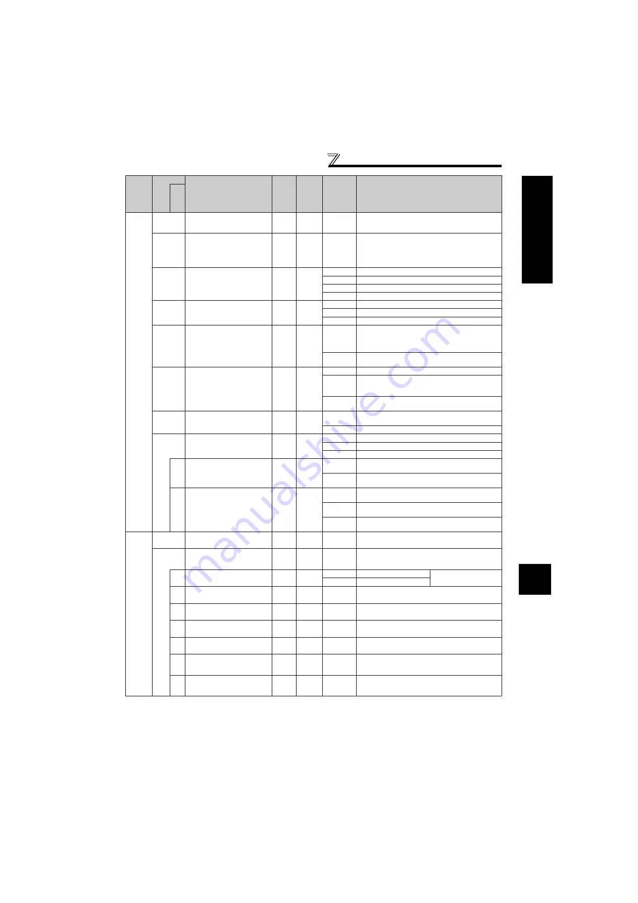
PU communication station
number
1
0
0 to 31
Specify the inverter station number.
Set the inverter station numbers when two or more
inverters are connected to one personal computer.
118
PU communication speed
1
192
48, 96, 192,
384
Set the communication speed.
The setting value
×
100 equals the communication
speed.
For example, the communication speed is 19200bps
when the setting value is "192".
119
PU communication stop bit
length
1
1
0
Stop bit length: 1bit data length: 8bit
1
Stop bit length: 2bit data length: 8bit
10
Stop bit length: 1bit data length: 7bit
11
Stop bit length: 2bit data length: 7bit
120
PU communication parity
check
1
2
0
Without parity check
1
With odd parity check
2
With even parity check
121
Number of PU
communication retries
1
1
0 to 10
Set the permissible number of retries at occurrence
of a data receive error.
If the number of consecutive errors exceeds the
permissible value, the inverter trips.
9999
If a communication error occurs, the inverter will not
come to trip.
122
PU communication check
time interval
0.1s
9999
0
No PU connector communication
0.1 to 999.8s
Set the communication check time interval.
If a no-communication state persists for longer than
the permissible time, the inverter trips.
9999
No communication check
(signal loss detection)
123
PU communication waiting
time setting
1
9999
0 to 150ms Set the waiting time between data transmission to the
inverter and response.
9999
Set with communication data.
124
PU communication CR/LF
selection
1
1
0
Without CR/LF
1
With CR
2
With CR/LF
342
Communication EEPROM
write selection
1
0
0
Parameter values written by communication are written
to the EEPROM and RAM.
1
Parameter values written by communication are
written to the RAM.
551
PU mode operation
command source selection
1
2
1
Select the RS-485 terminals as PU operation mode
control source.
2
Select the PU connector as PU operation mode
control source.
3
Select the USB connector as PU operation mode
control source.
Ch
ange of
analog
input
f
requency
,
adjust
m
ent
of
v
o
ltage,
c
u
rrent
input
and
fr
equency
(
calibrat
ion)
125
Terminal 2 frequency setting
gain frequency
0.01Hz
60Hz
0 to 400Hz Set the frequency of terminal 2 input gain
(maximum).
126
Terminal 4 frequency setting
gain frequency
0.01Hz
60Hz
0 to 400Hz
Set the frequency of terminal 4 input gain
(maximum).
(Valid when
Pr. 858
= 0 (initial value))
241
Analog input display unit
switchover
1
0
0
Displayed in %
Select the unit for analog
input display.
1
Displayed in V/mA
C2
(902)
Terminal 2 frequency setting
bias frequency
0.01Hz
0Hz
0 to 400Hz Set the frequency on the bias side of terminal 2 input.
C3
(902)
Terminal 2 frequency setting
bias
0.1%
0%
0 to 300% Set the converted % of the bias side voltage (current)
of terminal 2 input.
C4
(903)
Terminal 2 frequency setting
gain
0.1%
100%
0 to 300% Set the converted % of the gain side voltage of
terminal 2 input.
C5
(904)
Terminal 4 frequency setting
bias frequency
0.01Hz
0Hz
0 to 400Hz Set the frequency on the bias side of terminal 4 input.
(Valid when
Pr. 858
= 0 (initial value))
C6
(904)
Terminal 4 frequency setting
bias
0.1%
20%
0 to 300%
Set the converted % of the bias side current (voltage)
of terminal 4 input.
(Valid when
Pr. 858
= 0 (initial value))
C7
(905)
Terminal 4 frequency setting
gain
0.1%
100%
0 to 300%
Set the converted % of the gain side current (voltage)
of terminal 4 input.
(Valid when
Pr. 858
= 0 (initial value))
The parameter number in parentheses is the one for use with the parameter unit (FR-PU04/FR-PU07).
Func
tio
n
Parameter
Name
Incre
ments
Initial
Value
Range
Description
Re
la
te
d
p
ara
m
e
te
rs


