background image

10.

Always use tools that are in good condition and
be sure you understand how to use them before
performing any service work.

11.

Reinstall all fasteners with same part number.
Do not use a lesser quality fastener if
replacements are necessary.  Do not mix metric
fasteners with standard nuts and bolts.

12.

If possible, make all repairs with the truck
parked on a level, hard surface.  Block truck so it
does not roll while working on or under truck.

13.

Disconnect battery and discharge any capacitors
(electric trucks) before starting to work on truck.
Hang “Do not Operate” tag in the Operator’s
Compartment.

14.

Repairs, which require welding, should be
performed only with the benefit of the
appropriate reference information and by
personnel adequately trained and knowledgeable
in welding procedures.  Determine type of metal
being welded and select correct welding
procedure and electrodes, rods or wire to provide
a weld metal strength equivalent at least to that
of parent metal.

15.

Do not damage wiring during removal
operations.  Reinstall the wiring so it is not
damaged nor will it be damaged in operation by
contacting sharp corners, or by rubbing against
some object or hot surface.  Do not connect
wiring to a line containing fluid.

16.

Be sure all protective devices including guards
and shields are properly installed and functioning
correctly before starting a repair.  If a guard or
shield must be removed to perform the repair
work, use extra caution.

17.

Always support the mast and carriage to keep
carriage or attachments raised when maintenance
or repair work is performed, which requires the
mast in the raised position.

18.

Loose or damaged fuel, lubricant and hydraulic
lines, tubes and hoses can cause fires.  Do not
bend or strike high pressure lines or install ones
which have been bent or damaged.  Inspect lines,
tubes and hoses carefully.  Do not check for
leaks with your hands.  Pin hole (very small)
leaks can result in a high velocity oil stream that
will be invisible close to the hose.  This oil can
penetrate the skin and cause personal injury.  Use
cardboard or paper to locate pin hole leaks.

19.

Tighten connections to the correct torque.  Make
sure that all heat shields, clamps and guards are
installed correctly to avoid excessive heat,
vibration or rubbing against other parts during
operation.  Shields that protect against oil spray
onto hot exhaust components in event of a line,
tube or seal failure, must be installed correctly.

20.

Relieve all pressure in air, oil or water systems
before any lines, fittings or related items are
disconnected or removed.  Always make sure all
raised components are blocked correctly and be
alert for possible pressure when disconnecting
any device from a system that utilizes pressure.

21.

Do not operate a truck if any rotating part is
damaged or contacts any other part during
operation.  Any high speed rotating component
that has been damaged or altered should be
checked for balance before reusing.

Содержание FB16NT

Страница 1: ...Service Manual 99759 5B110 Chassis Mast Options FB16NT EFB11 20011 up FB18NT EFB13 20011 up FB20NT EFB13 70001 up MC FC For use with FB16NT FB20NT Controller Service Manual...

Страница 2: ...ifications contained in this manual are for trucks with serial numbers in effect at the time of printing Mitsubishi forklift trucks reserves the right to change specifications or design without notice...

Страница 3: ...name Suggestion for disassembly 1 Output shaft removal Unit mm in A 0 020 to 0 105 Clearance between 0 00079 to 0 00413 cylinder and piston 0 15 B 0 0059 A Standard value B Repair or service limit Dis...

Страница 4: ...this truck This makes it important to use caution when performing service work A knowledge of the system and or components is important before the removal or disassembly of any component Because of t...

Страница 5: ...f a guard or shield must be removed to perform the repair work use extra caution 17 Always support the mast and carriage to keep carriage or attachments raised when maintenance or repair work is perfo...

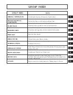
Страница 6: ...sembly and reassembly BRAKE SYSTEM STEERING SYSTEM Rear axle Rear wheels Caliper Brake pedal Master cylinder Steering control valve HYDRAULIC SYSTEM MASTS AND FORKS Tank Pump Control valve Lift and ti...

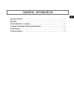
Страница 7: ...Vehicle Exterior 1 1 Models 1 1 Serial Number Locations 1 2 Chassis and Mast Model Identification 1 3 Dimensions 1 4 Technical Data 1 5 1 GENERAL INFORMATION...

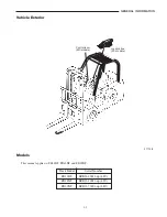
Страница 8: ...B16NT EFB11 20011 up 48V FB18NT EFB13 20011 up 48V FB20NT EFB13 70001 up 48V 1 1 GENERAL INFORMATION 211128 Vehicle Exterior Models This manual applies to FB16NT FB18NT and FB20NT Joystick box FC mode...

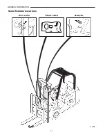
Страница 9: ...1 2 GENERAL INFORMATION Mast number Chassis number Nameplate 211268 Serial Number Locations...

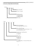
Страница 10: ...4400 lb Maximum lifting height 30 stands for 3000 mm 118 in Order of the minor change A for the original B for the first change C for the second change and so on Applicable truck model designation 15...

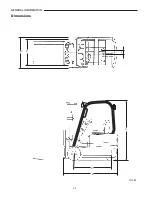
Страница 11: ...1 4 GENERAL INFORMATION Dimensions B E F A D C 211269...

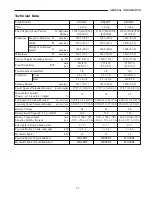
Страница 12: ...10 Rear 15 4 5 8 15 4 5 8 140 55 9 Turning Radius mm in 1517 59 7 1620 63 8 1645 64 8 Travel Speeds Unloaded Loaded km h mph 17 17 10 6 10 6 17 17 10 6 10 6 17 17 10 6 10 6 Gradeability Loaded 27 25...

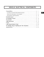
Страница 13: ...ponents in Console Box 2 5 Disassembly and Reassembly 2 6 Direction Lever 2 7 Accelerator Control 2 8 Key Switch 2 9 Lighting Switch 2 9 Fuses 2 10 Lamp Specification Chart 2 10 Troubleshooting of Lig...

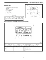
Страница 14: ...light fastened when 2 operator sits on seat seat switch is turned on 2 1 VEHICLE ELECTRICAL COMPONENTS Console Box 1 Central vehicle monitoring system CVMS 2 Mode selector button 3 Steering tilt lever...

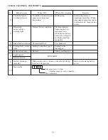
Страница 15: ...attery needs to be warning light recharged soon 4 ON indicates battery needs to be recharged and lifting function inoperable 5 Brake fluid level indicator Normal fluid level Low fluid level 6 Parking...

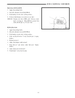
Страница 16: ...ock until it is changed When MPH is selected the clock will change to a 12 hour clock Setting the clock 1 Apply the parking brake 2 Place the direction lever in NEUTRAL 3 Turn the key switch to the I...

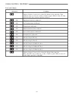
Страница 17: ...erheated ON Right traction inverter overheated ON Left traction inverter overheated ON Pump inverter overheated ON Faulty setting of lift lever ON Faulty setting of tilt lever ON Faulty setting of att...

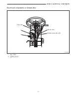
Страница 18: ...2 5 VEHICLE ELECTRICAL COMPONENTS Electrical Components in Console Box 2 1 Horn cable Monitor cable Direction lever switch cable 1 Key switch 2 Lighting switch 211132...

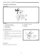
Страница 19: ...panel 6 Key switch 7 Light switch Disassembly procedure 1 Remove the front panel and monitor panel from the console box 2 Disconnect the harness connectors from the horn and direction lever 3 Remove t...

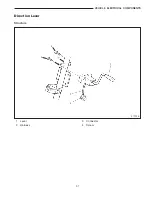
Страница 20: ...2 7 VEHICLE ELECTRICAL COMPONENTS Direction Lever Structure 1 2 3 4 4 211135 1 Lever 2 Harness 3 Connector 4 Screw...

Страница 21: ...BUY NOW Then Instant Download the Complete Manual Thank you very much...

Отзывы: