


Table 2.2 General-purpose output specifications
Transistor output (sink type)
AJ65BT-R2 External
connection
No. of output points
2 points
Insulation method
Photo coupler insulation
Rated load voltage
12/24VDC
Working load voltage
range
10.2 to 28.8VDC
(ripple rate within 5%)
Max. load current
0.1A/point 0.2A/common
Max. rush current
0.4A 10ms or less
Leakage current at
OFF
0.1mA or less
Max. voltage drop at
ON
1.5VDC or less (MAX) 0.1A
Output type
Sink type
OFF
ON 2ms or less
Response
time
ON
OFF 2ms or less (resistance load)
Voltage 10.2
to
28.8VDC
(ripple rate within 5%)
Output
section
externally
supplied
power
Current 50mA or less (TYP. 24VDC,
per common)
Not including external load
current.
Surge killer
Zener diode
Common method
2 points/common (COM2)
6
COM2
7 YD
5 YC
L
L
12/24VDC
Int
er
nal
cir
cu
it
External connection
method
9-pin connector (I/O section)
7-point terminal block (M3.5
screw)
Including transmission circuit
and module power terminal
Terminal
No.
Signal
name
Terminal
No.
Signal
name
Applicable wire size
0.75 to 2mm
2
TB5
YC
TB7
YD
Applicable crimp
terminal
RAV1.25-3.5, RAV2-3.5 (JIS C
2805 compliant)
TB6 COM2
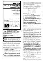
3. Part Names and Settings
(1)
(3) (2)
(7)
(6)
(8)
(9)
(5)
(4)
(10)
No. Name
Details
LED name
Details
PW
ON
: Power is ON.
OFF
: Power is OFF.
RUN
ON
: Operating normally
OFF
: Power (24VDC) is OFF or WDT error is
occurring.
Default
state
L RUN
ON
: Communicating normally
OFF
: Communication stopped (Time over
error)
State L
ERR.
ON : Any transmission speed or station
number out of range is set.
Flickering at constant intervals :
The transmission speed or station number
has been changed after the power is
turned on.
Flickering not constant intervals :
The terminating resistor is not connected.
The module or CC-Link dedicated cable is
being affected by noise.
OFF: Communicating normally
SD
ON : Data link Sending data
OFF : Data link Not sending data
Others
RD
ON : Data link Receiving data
OFF : Data link Not receiving data
XC, XD
ON : General-purpose input (XC, XD) is ON.
OFF : General-purpose input (XC, XD) is OFF.
YC, YD
ON : General-purpose output (YC, YD) is ON.
OFF : General-purpose output (YC, YD) is OFF.
RS-232-C SD
ON : Sending RS-232C data
OFF : Not sending RS-232C data
RS-232-C RD
ON : Receiving RS-232C data
OFF : Not receiving RS-232C data
(1) Operation display
LEDs
RS-232-C ERR.
ON : RS-232C transmission error
OFF : No error
No.
Name
Details
(2) Station No. setting
switch
Set the module's station No. (Default setting: 0)
Setting range: 1 to 64 (0: Master module)
"
10" sets the 10th place of the station No..
"
1" sets the 1st place of the station No..
Setting
Transmission
speed
0 156kbps
1 625kbps
2 2.5Mbps
3 5Mbps
4 10Mbps
(3) Data link transmission
speed setting switch
5 to 9
Setting error
Set the module's transmission speed
(for data link)
(Default setting: 0)
Set the module's operation state. (Default setting: 0)
No.
Name Setting
details
0
On-line mode
(using transmission/
reception buffer)
Mode for on-line communication.
Set when using the
transmission/reception buffer.
1
On-line mode
(using buffer
memory automatic
update function)
Mode for on-line communication.
Set when using the buffer memory
automatic update function.
2 Not used
Setting error ("RUN" LED turns OFF.)
3 Not used
Setting error ("RUN" LED turns OFF.)
4 Use
not
possible
–
5 Not used
Setting error ("RUN" LED turns OFF.)
6 Not used
Setting error ("RUN" LED turns OFF.)
7 Not used
Setting error ("RUN" LED turns OFF.)
8 Not used
Setting error ("RUN" LED turns OFF.)
9 Not used
Setting error ("RUN" LED turns OFF.)
A Not used
Setting error ("RUN" LED turns OFF.)
B Not used
Setting error ("RUN" LED turns OFF.)
C Not used
Setting error ("RUN" LED turns OFF.)
D
Hardware test
mode
Mode for confirming that module runs
independently.
E Not used
Setting error ("RUN" LED turns OFF.)
(4) Mode setting switch
F Not used
Setting error ("RUN" LED turns OFF.)
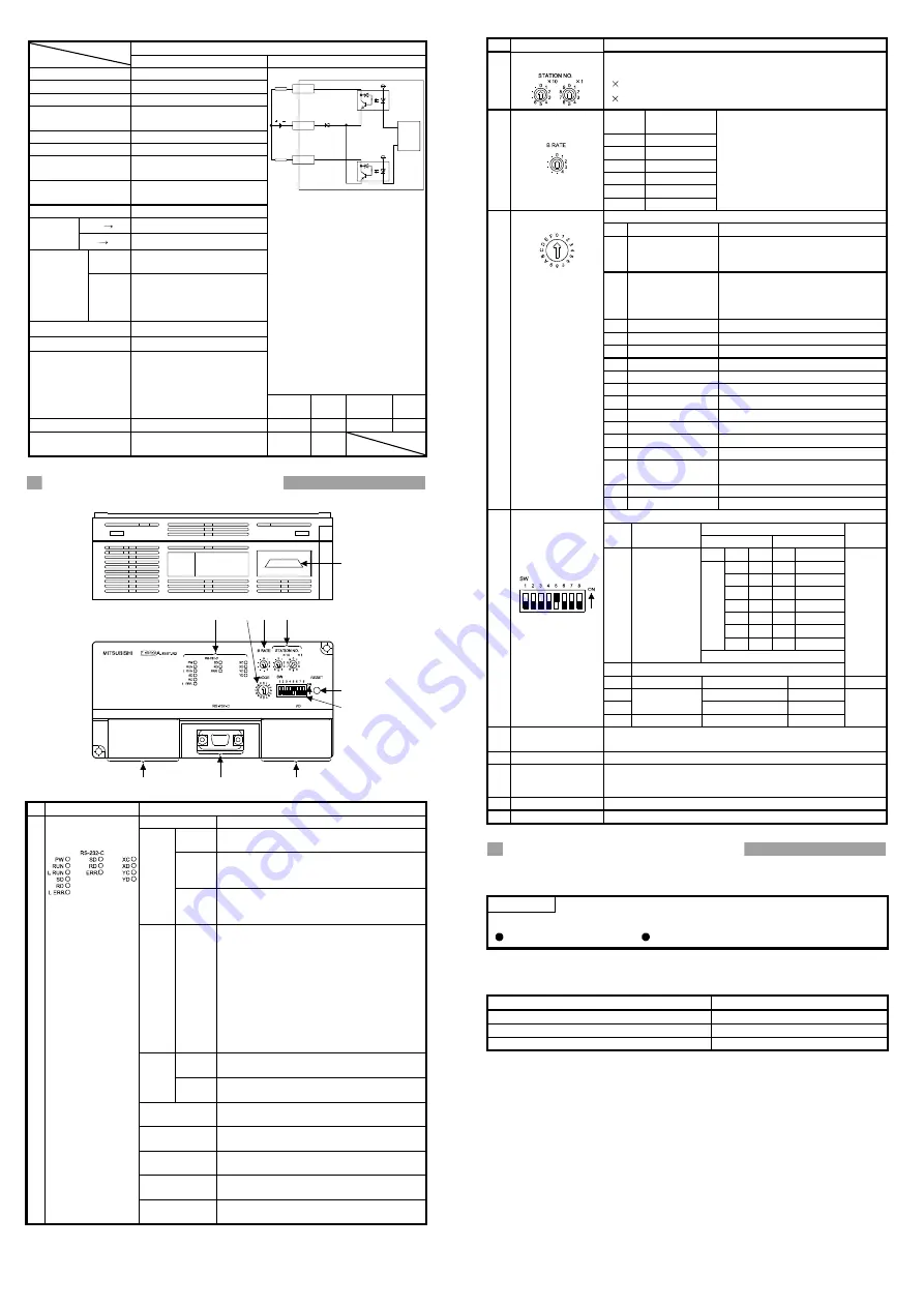
Set the RS-232C transmission specifications.
Setting switch state
No. Setting
details
ON OFF
Default
setting
SW 1 2 3
0 0 0 300bps
1 0 0 600bps
0 1 0 1200bps
1 1 0 2400bps
0 0 1 4800bps
1 0 1 9600bps
0 1 1
19200bps
SW1
to 3
Transmission
speed
0:OFF
1:ON
SW4
Not used
OFF
SW5 Data bit length
8
7
ON
SW6
Yes No
SW7
Parity bit
Even Odd
(5) RS-232C
transmission
specifications setting
switch
SW8 Stop bit length
2
1
OFF
(6) Data link terminal
block
Connect a CC-Link dedicated cable for power supply and data
link. (2-piece terminal block)
(7) RS-232C interface
Connect an RS-232C cable for connection with external device.
(8) General-purpose
input/output terminal
block
Connect the input/output wire.
(9) Reset switch
Returns to the power ON status.
(10) Connector
Use prohibited.
4. Mounting and Installation
4.1 Precautions for handling
POIN
T
For handling instructions such as module installation/removal, read
SAFETY PRECAUTIONS given at the beginning of this manual.
(1) Tighten the module installation screws and terminal block screws
within the following range.
Screw place
Tightening torque range
Module installation screw (M4 screw)
0.78 to 1.18N
y
m
Terminal block terminal screw (M3.5 screw)
0.59 to 0.88N
y
m
Terminal block installation screw (M4 screw)
0.98 to 1.37N
y
m
(2) When using the DIN rail adaptor, install the DIN rail while observing
the following points.
(a) Applicable DIN rail type (JIS C 2812 compliant)
TH35-7.5Fe
TH35-7.5Al
TH35-15Fe
(b) DIN rail installation screw pitch
When installing the DIN rail, tighten the screws at a pitch of
200mm or less.
4.2 Installation environment
When installing the PLC, refer to the CC-Link system master module's
User's Manual.


