Mitsubishi Heavy Industries SRK71VNPZM Скачать руководство пользователя страница 67

-

62 

-

 '13 • PAC-DB-194

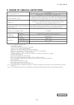
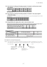
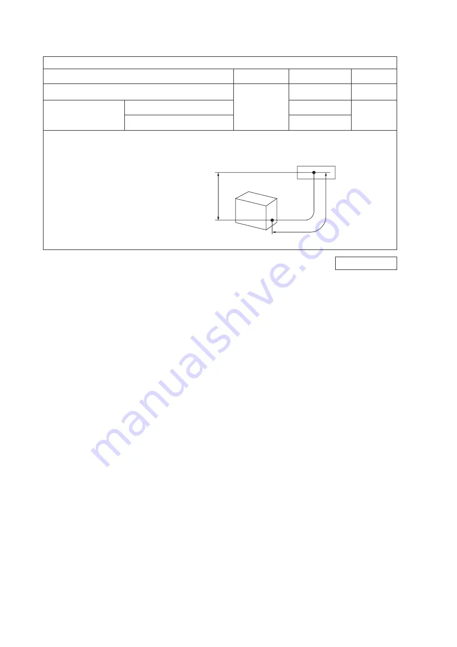
Limitation on unit and piping installation

Descriptions

Model for

outdoor unit

Dimensional limitations Marks appearing

in the drawing

One-way pipe length

FDC71VNP

FDC

90

VNP

≦ 

30m

(2)

L

H

Elevation difference between

indoor and outdoor unit

When the outdoor unit is positioned higher

20m

When the outdoor unit is positioned lower

20m

Notes(1) FDC71VNP, 90VNP can be used for only single type.

(2)

In case of FDF series, one way pipe length is not greater than 23m.

H

L

Outdoor unit

Indoor unit

PJF000Z317

PJF000Z317

   #

Содержание SRK71VNPZM

Страница 1: ...HIGH STATIC PRESSURE TYPE FDU71VNPVF1 FDU90VNPVF1 FDU90VNPVF2 FLOOR STANDING TYPE FDF71VNPVD1 FDF90VNPVD1 FDF90VNPVD2 WALL MOUNTED TYPE SRK71VNPZM DUCT CONNECTED LOW MIDDLE STATIC PRESSURE TYPE FDUM71VNPVF1 FDUM90VNPVF1 FDUM90VNPVF2 Service code 1 L to comply with amended safety standard for LVD Outdoor unit Changes History of service code FDC71VNP 1 L FDC90VNP 1 L Manual No 13 PAC DB 194 updated ...

Страница 2: ... Middle static pressure type FDUM 89 3 Duct connected High static pressure type FDU 83 3 Floor standing type FDF 57 3 EXTERIOR DIMENSIONS 22 1 Indoor units 22 2 Outdoor units 32 4 ELECTRICAL WIRING 37 5 NOISE LEVEL 47 6 CHARACTERISTICS OF FAN 50 7 TEMPERATURE AND VELOCITY DISTRIBUTION 53 8 PIPING SYSTEM 58 9 RANGE OF USAGE LIMITATIONS 60 1 Indoor units 37 2 Outdoor units 45 1 Indoor units 47 2 Out...

Страница 3: ...series RCN T 36W E 144 2 FDEN series RCN E1R 146 3 FDU FDUM FDF series RCN KIT3 E 150 144 13 TECHNICAL INFORMATION 166 2 Ceiling suspended type FDEN 168 1 Ceiling cassette 4way type FDT 166 4 Duct connected Low Middle static pressure type FDUM 172 3 Duct connected High static pressure type FDU 170 5 Floor standing type FDF 174 6 Wall mounted type SRK 176 How to read the model name FDT Ceiling cass...

Страница 4: ...test model SRK ZM S 3HP FDC71VNX FDT71VF FDEN71VF FDUM71VF FDU71VD FDF71VD OK FDT71VF1 FDEN71VF1 FDUM71VF1 FDU71VF1 FDF71VD1 OK SRK71 ZM S N A FDC71VNP N A OK OK 3 5HP FDC90VNP FDT100VF FDEN100VF FDUM100VF FDU100VD FDF100VD N A FDT100VF1 FDEN100VF1 FDUM100VF1 FDU100VF1 FDF100VD1 OK N A 4HP FDC100VN VS FDC100VNX VSX OK OK 100 capacity indoor units can be connected to 3 5HP Connectable indoor unit F...

Страница 5: ...0 20 20 O U below m 15 20 20 Operation range Cooling deg C 15 43 15 46 15 46 Heating deg C 20 20 15 21 15 20 2 2 3 5HP Specification Hyper Micro New FDC100VNX FDC100VN FDC90VNP FDT100VF1 FDT100VF1 FDT100VF1 Power supply V 50Hz 220 240V 60Hz 220V 50Hz 220 240V 60Hz 220V 50Hz 220 240V 60Hz 220V Cooling Capacity Nominal kW 10 0 10 0 9 0 Range kW 4 0 11 2 4 0 11 2 1 9 9 0 EER 4 00 3 62 3 37 SEER 5 84 ...

Страница 6: ...EER COP SCOP FDC71VNX SRC71ZK S FDC71VNP 0 1 2 3 4 5 6 7 8 EER SEER COP SCOP FDC100VNX FDC100VN FDC90VNP 3 2 Efficiency 1 3HP 2 3 5HP EER energy efficiency ratio efficiency of cooling COP coefficient of performance efficiency of heating SEER SCOP Seasonal EER Seasonal COP defined by European standard EN14825 It shows annual efficiency according to European climate condition Average Nominal efficie...

Страница 7: ...n 3 4 Pipe size and Piping length both 1rank down Liquid pipe 1rank down Shorter Shorter Pipe size becomes smaller easy to install Pipe length becomes shorter limit the installation flexibility 1 3HP 2 3 5HP If indoor unit is FDF series chargeless pipe length 8m max pipe length 23m Liquid pipe 1rank down Shorte HP 0 2 4 6 8 10 12 14 16 18 Pipe size liquid Pipe size gas FDC71VNX SRC71ZK S FDC71VNP ...

Страница 8: ...ng diameter D6 35 D12 7 Gas Liquid D6 35 D9 52 D12 7 D15 88 D6 35 D15 88 D6 35 D9 52 Reducer attached in O U Pipe diameter adjustment is necessary near indoor unit Liquid side is not necessary in case of SRK 3 5 Piping system 1 3HP Hyper New Muffler Crank case heater ...

Страница 9: ...13 PAC DB 194 2 3 5HP Hyper Crank case heater New 4 1 Combination Outdoor units do not have plural control Plural combination is prohibited Single only Plural control FDT40VF1 NO FDC71VNP 4 Other features ...

Страница 10: ...C 100 35 43 85 Maximum capacity of other series FDC71VNP FDC90VNP Cooling 42 44 46 48 50 52 54 56 58 Sound pressure level dB A FDC100VNX FDC100VN FDC90VNP FDC90VNP silent mode 4 3 Sound level 4 4 Trial operation No DIP switch for trial operation Sound pressure level becomes higher Silent mode is prepared note capacity down to around 90 1 3HP 2 3 5HP ...

Страница 11: ...nance Relay cable is necessary New RAM file is also needed RAMDATA_eR25V xls FD CONVERTER PCA006A075B 4pin 8pin CNROM white Cable PCZ504A065A PCB 2 Inverter checker is possible for maintenance Short connector is necessary Short between Pin No 2 and No 3 of CNROM CNROM ...

Страница 12: ...Compressor Electric heater W Operation control Remote control option wired RC EX1A RC E5 RCH E3 wireless RCN T 36W E Room temperature control Thermostat by electronics Operation display Safety equipments Compressor overheat protection Overcurrent protection Frost protection Serial signal error protection Indoor fan motor error protection Heating overload protection High pressure control Cooling ov...

Страница 13: ...ressor Electric heater W Operation control Remote control option wired RC EX1A RC E5 RCH E3 wireless RCN T 36W E Room temperature control Thermostat by electronics Operation display Safety equipments Compressor overheat protection Overcurrent protection Frost protection Serial signal error protection Indoor fan motor error protection Heating overload protection High pressure control Cooling overlo...

Страница 14: ...essor Electric heater W Operation control Remote control option wired RC EX1A RC E5 RCH E3 wireless RCN T 36W E Room temperature control Thermostat by electronics Operation display Safety equipments Compressor overheat protection Overcurrent protection Frost protection Serial signal error protection Indoor fan motor error protection Heating overload protection High pressure control Cooling overloa...

Страница 15: ...ration control Remote control option wired RC EX1A RC E5 RCH E3 wireless RCN E1R Room temperature control Thermostat by electronics Operation display RUN Green TIMER Yellow CHECK Yellow Safety equipments Compressor overheat protection Overcurrent protection Frost protection Serial signal error protection Indoor fan motor error protection Heating overload protection High pressure control Cooling ov...

Страница 16: ...W 0 Operation control Remote control option wired RC EX1A RC E5 RCH E3 wireless RCN E1R Room temperature control Thermostat by electronics Operation display RUN Green TIMER Yellow CHECK Yellow Safety equipments Compressor overheat protection Overcurrent protection Frost protection Serial signal error protection Indoor fan motor error protection Heating overload protection High pressure control Coo...

Страница 17: ...t by electronics Operation display Safety equipments Compressor overheat protection Overcurrent protection Frost protection Serial signal error protection Indoor fan motor error protection Heating overload protection High pressure control Cooling overload protection Installation data Refrigerant piping size O D mm Liquid line I U φ 9 52 3 8 Pipe φ 6 35 1 4 0 8 O U φ 6 35 1 4 Gas line I U φ 15 88 5...

Страница 18: ...at by electronics Operation display Safety equipments Compressor overheat protection Overcurrent protection Frost protection Serial signal error protection Indoor fan motor error protection Heating overload protection High pressure control Cooling overload protection Installation data Refrigerant piping size O D mm Liquid line I U φ 9 52 3 8 Pipe φ 6 35 1 4 0 8 O U φ 6 35 1 4 Gas line I U φ 15 88 ...

Страница 19: ...at by electronics Operation display Safety equipments Compressor overheat protection Overcurrent protection Frost protection Serial signal error protection Indoor fan motor error protection Heating overload protection High pressure control Cooling overload protection Installation data Refrigerant piping size O D mm Liquid line I U φ 9 52 3 8 Pipe φ 6 35 1 4 0 8 O U φ 6 35 1 4 Gas line I U φ 15 88 ...

Страница 20: ...tat by electronics Operation display Safety equipments Compressor overheat protection Overcurrent protection Frost protection Serial signal error protection Indoor fan motor error protection Heating overload protection High pressure control Cooling overload protection Installation data Refrigerant piping size O D mm Liquid line I U φ 9 52 3 8 Pipe φ 6 35 1 4 0 8 O U φ 6 35 1 4 Gas line I U φ 15 88...

Страница 21: ... by electronics Operation display Safety equipments Compressor overheat protection Overcurrent protection Frost protection Serial signal error protection Indoor fan motor error protection Heating overload protection High pressure control Cooling overload protection Installation data Refrigerant piping size O D mm Liquid line I U φ 9 52 3 8 Pipe φ 6 35 1 4 0 8 O U φ 6 35 1 4 Gas line I U φ 15 88 5 ...

Страница 22: ...t by electronics Operation display Safety equipments Compressor overheat protection Overcurrent protection Frost protection Serial signal error protection Indoor fan motor error protection Heating overload protection High pressure control Cooling overload protection Installation data Refrigerant piping size O D mm Liquid line I U φ 9 52 3 8 Pipe φ 6 35 1 4 0 8 O U φ 6 35 1 4 Gas line I U φ 15 88 5...

Страница 23: ...lectric heater W Operation control Remote control RC E5 Installed wireless RCN KIT3 E option Room temperature control Thermostat by electronics Operation display Safety equipments Compressor overheat protection Overcurrent protection Frost protection Serial signal error protection Indoor fan motor error protection Heating overload protection High pressure control Cooling overload protection Instal...

Страница 24: ...Electric heater W Operation control Remote control RC E5 Installed wireless RCN KIT3 E option Room temperature control Thermostat by electronics Operation display Safety equipments Compressor overheat protection Overcurrent protection Frost protection Serial signal error protection Indoor fan motor error protection Heating overload protection High pressure control Cooling overload protection Insta...

Страница 25: ... Electric heater W Operation control Remote control RC E5 Installed wireless RCN KIT3 E option Room temperature control Thermostat by electronics Operation display Safety equipments Compressor overheat protection Overcurrent protection Frost protection Serial signal error protection Indoor fan motor error protection Heating overload protection High pressure control Cooling overload protection Inst...

Страница 26: ...ater W Operation control Remote control Wireless Remote control Room temperature control Thermostat by electronics Operation display RUN Green TIMER Yellow HI POWER Green ECONO Orange Safety equipments Compressor overheat protection Overcurrent protection Frost protection Serial signal error protection Indoor fan motor error protection Heating overload protection High pressure control Cooling over...

Страница 27: ...0 or more between the units when installing more than one Obstacle or more or more Space for installation and service G Holes for tapping screws Hole 5 φ4 Holes for tapping screws 6 φ4 Hole Max Drain lift or less box Control Ceiling hole size Suspension bolts pitch Suspension bolts pitch Accessory Installed on site Drain hose piece suspension bolt Hanger plate for Control box or more 778 860 910 7...

Страница 28: ...ducting for ducting Space for installation and service Knock out Knock out G Holes for tapping screws Hole 5 φ4 Holes for tapping screws 6 φ4 Hole Decorative panel Ceiling hole size Suspension bolts pitch Suspension bolts pitch C Installed on site Drain hose piece suspension bolt Hanger plate for Control box or more Max Drain lift or less box Control 778 860 910 725 648 418 420 50 150 207 260 303 ...

Страница 29: ...ly Receiving part Note The slope of drain piping inside the unit must take decline of 10mm Drain hose piece Accesory 0 3m Installed on site Liquid piping Gas piping Top cutout Back cutout Hole for suspension bolts Drain piping B F E Symbol D C1 2 A PE cover Content M10 or M8 VP20 I D 20 O D 26 φ9 52 3 8 Flare φ15 88 5 8 Flare Plate cover or more or more or more Hole for drain piping for left back ...

Страница 30: ...the cutout using side cutter or similar tool Obstacle Space for installation and service or more Air return grille Air supply Drain hose piece Accesory 0 3m Installed on site or more or more Plate cover or more Hole for drain piping for left back G Knock out for left drain piping Hole for Unit mm 290 Suspension bolts pitch Suspension bolts pitch 68 410 690 76 75 110 135 308 300 100 1572 1540 1620 ...

Страница 31: ...ce refer to page 88 b Install refrigerant pipes drain pipe and wiring so as not to cross marked area c The case that pipes are installed to upper bottom of fan unit keep space of 60mm or more to upper bottom of unit Pipe c Fan unit View M tapping screws Holes for Hole φ170 φ124 φ170 tapping screws Holes for C1 Drain piping VP25 I D 25 O D 32 F Outside air opening Air outlet opening G for ducting f...

Страница 32: ...le to draw out 2 fan units For fan units maintenance refer to page 88 b Install refrigerant pipes drain pipe and wiring so as not to cross marked area c The case that pipes are installed to upper bottom of fan unit keep space of 60mm or more to upper bottom of unit C1 Drain piping VP25 I D 25 O D 32 VP20 I D 20 O D 26 Unit mm 4 φ4 Suspension bolts pitch Air supply duct Control box Duct dimension D...

Страница 33: ...ached on the lid of the control box Case 2 From bottom of unit or more or more Notes a There must not be obstacle to draw out fan unit For fan unit maintenance refer to page 94 b Install refrigerant pipes drain pipe and wiring so as not to cross marked area c The case that pipes are installed to upper bottom of fan unit keep space of 60mm or more to upper bottom of unit VP25 I D 25 O D 32 VP20 I D...

Страница 34: ... attached on the lid of the control box Notes a There must not be obstacle to draw out 2 fan units For fan units maintenance refer to page 94 b Install refrigerant pipes drain pipe and wiring so as not to cross marked area c The case that pipes are installed to upper bottom of fan unit keep space of 60mm or more to upper bottom of unit C1 Drain piping VP25 I D 25 O D 32 VP20 I D 20 O D 26 Unit mm ...

Страница 35: ...5 50 φ100 Knock out Hole on wall for rear piping 4 7 25 Slot Fresh air intake Both left and right Hole on wall for side piping M8 2 places φ100 Knock out φ100 Resin cap having VP20 I D 20 O D 26 Fall prevention metal fittings Metal fittings to fix to floor face Hole on wall for bottom piping Drain piping Liquid piping Gas piping H G F E D C B A Content Symbol φ9 52 3 8 Flare φ15 88 5 8 Flare 143 8...

Страница 36: ...5 8 Flare φ65 Note 1 The model name label is attached on the underside of the panel D C B A E Wireless remote control Wired Remote control Option G F Unit mm 77 53 5 633 5 703 5 792 15 7 7 44 5 44 5 301 8 8 5 50 50 450 349 299 106 886 106 65 100 50 49 5 221 5 25 25 Service space Service space Service space Unit Installation plate Space for installation and service when viewing from the front 6 5X1...

Страница 37: ...8 4 12 4 351 6 L2 L3 L4 L1 100 100 250 Open I Ⅱ Ⅲ Ⅳ Open 250 80 280 280 Open 80 75 Examples of Dimensions installation 180 Open 80 Open 38 6 90 6 520 6 16 35 6 Notes 1 It must not be surrounded by walls on the four sides 2 The unit must be fixed with anchor bolts An anchor bolt must not protrude more than 15mm 3 Where the unit is subject to strong winds lay it in such a direction that the blower o...

Страница 38: ...dominant wind direction 4 Leave 1m or more space above the unit 5 A wall in front of the blower outlet must not exceed the unit s height 6 The model name label is attached on the lower right corner of the front panel Minimum installation space D C E Symbol Content A Service valve connection gas side φ15 88 5 8 Flare B Service valve connection liquid side φ6 35 1 4 Flare C Pipe cable draw out hole ...

Страница 39: ...ring thickness 100 to 200m 0 5mm2 2 cores 0 75mm2 2 cores 1 25mm2 2 cores 2 0mm2 2 cores Under 300m Under 400m Under 600m Upper part Lower part Lower case Sheath Upper cace Board Wiring Upper Lower X Y Sheath Upper cace Board Wiring Upper Lower Y X Tighten the screws after cutting off the thin part of screw mounting part Embedded mounting The peeling off length of sheath The peeling off length of ...

Страница 40: ... 35 13 PAC DB 194 Model RC EX1A Except SRK series Installation space R C cable 0 3mm2 2 core Adapted to RoHS directive Exterior appearance Munsell color Pearl White N8 5 near equivalent a PJZ000Z297 ...

Страница 41: ... 36 13 PAC DB 194 b Wireless remote control Unit mm Unit mm RCN E1R Option parts Except SRK series SRK series only Standard accessory 60 17 150 60 26 167 ...

Страница 42: ...2 11 12 DM RD WH 1 2 CNR WH CNW1 WH M WH WH WH WH WH WH WH WH WH WH WH 1 2 3 4 5 6 1 2 3 4 CNV2 BK CNTA BL 1 2 SW8 BL WH 1 3 CNW3 WH CNW2 WH CNWR2 WH L Drain motor Fan motor DM Louver motor Float switch LM1 4 FS Fuse F1 3 Connector CNB Z LED 2 Operation check Drain motor test run Thermistor Remote control Model capacity setting SW6 Terminal block Power source 口mark TB1 TB2 Indication lamp Green No...

Страница 43: ...ote control BK BK BK BK XR5 Remote operation input volt free contact Operation Heating Compressor ON Inspection Prepare on site Closed end connector mark Control PCB Color Mark BK Color Marks Black BL Blue BR Brown Color Mark RD Red WH White YE GN Yellow Green Receiver PCB 7 segment display Switches for setting SW1 LED2 Back up switch Operation Stop SW4 Indication lamp Green Normal operation LED3 ...

Страница 44: ... 3 4 5 6 12 SW2 SW6 SW5 SW7 LED 2 LED 3 X Y 1 3 X Y t TB2 WH BK WH 8 9 10 11 12 8 9 10 11 12 CNW2 WH CNW1 WH CNB WH CNN YE CNH BK CNT BL 1 2 WH RD YE GN F1 5A 3 5 CNW0 WH 1 TB1 Power circuit Operation Heating Compressor ON Inspection 3 ThC Earth Power source line Signal line 1 2 3 indoor unit and outdoor unit Connecting line between WH WH WH WH Remote control input volt free contact WH WH WH WH WH...

Страница 45: ...CB RD YE t YE BK t BK 1 2 3 4 5 6 BK t BK 1 2 XR1 XR2 XR3 XR4 XR5 Remote operation 1 2 3 4 5 6 12 SW2 SW6 SW5 SW7 LED 2 LED 3 X Y 1 3 X Y t TB2 WH BK WH 8 9 10 11 12 8 9 10 11 12 CNW2 WH CNW1 WH CNB WH CNN YE CNH BK CNT BL 1 2 WH RD YE GN 3 5 CNW0 WH 1 TB1 Power circuit Operation Heating Compressor ON Inspection 3 ThC WH WH WH WH Remote control input volt free contact WH WH WH WH WH WH WH WH 3 4 5...

Страница 46: ...M FS CNZ For HA WH M 1 2 CNTA BL 1 2 RD t Control PCB Power PCB RD YE t YE BK t BK 1 2 3 4 5 6 BK t BK 1 2 XR1 XR2 XR3 XR4 XR5 Remote operation input volt free contact Prepare on site 1 2 3 4 5 6 12 SW2 SW6 SW5 SW7 LED 2 LED 3 X Y 1 3 X Y t TB2 WH BK WH 8 9 10 11 12 8 9 10 11 12 CNW2 WH CNW1 WH CNB WH CNN YE CNH BK CNT BL 1 2 WH RD YE GN 3 5 CNW0 WH 1 TB1 Power circuit Operation Heating Compressor...

Страница 47: ...r HA WH M 1 2 CNTA BL 1 2 RD t Control PCB Power PCB RD YE t YE BK t BK 1 2 3 4 5 6 BK t BK 1 2 XR1 XR2 XR3 XR4 XR5 Remote operation input volt free contact Prepare on site 1 2 3 4 5 6 12 SW2 SW6 SW5 SW7 LED 2 LED 3 X Y 1 3 X Y t TB2 WH BK WH 8 9 10 11 12 8 9 10 11 12 CNW2 WH CNW1 WH CNB WH CNN YE CNH BK CNT BL 1 2 WH RD YE GN 3 5 CNW0 WH 1 TB1 Power circuit Operation Heating Compressor ON Inspect...

Страница 48: ...Thermistor Return air Thc ThI R1 2 3 ThI A TB2 Terminal block Signal line 口mark Relay for DM X4 TB1 Terminal block Power source mark Plural units Master Slave setting CNZ BK t Control PCB Power PCB BK BK t BK GR t GR 1 2 3 4 5 6 BK t BK 1 2 XR1 XR2 XR3 XR4 XR5 Remote operation input volt free contact Prepare on site 1 2 3 4 5 6 12 SW6 SW5 SW7 X Y 1 3 X Y t TB2 WH BK RD 1 2 3 4 5 1 2 3 4 5 CNW3 RD ...

Страница 49: ...2 Th3 LM1 LM2 SM1 FMI DS t t TO OUTDOOR UNIT HEAT EXCHANGER 1 2 N 3 POWER WIRES SIGNAL WIRE 1 2 N 3 Power source 220 230 240V 50Hz T 8 Color Marks Blue Black BK Red BL RD White WH Yellow Green Y G Yellow Y Color Mark Heat exch sensor Humidity sensor Fan motor Room temp sensor Flap motor Th1 Th21 2 Th3 Diode stack DS Fuse F Connector CNE CNX2 FMI Terminal block T Louver motor LM1 2 SM1 Description ...

Страница 50: ...fications are based on the assumption that a metal or plastic conduit is used with no more than three cables contained in a conduit and a voltage drop is 2 For an installation falling outside of these conditions please follow the internal cabling regulations Adapt it to the regulation in effect in each country 14 5 2 0 15 1 5mm2 x 4 1 5 71 3 1 2 N S BK WH RD V W U PWB ASSY MAIN M M R TRANSISTOR PO...

Страница 51: ...ations are based on the assumption that a metal or plastic conduit is used with no more than three cables contained in a conduit and a voltage drop is 2 For an installation falling outside of these conditions please follow the internal cabling regulations Adapt it to the regulation in effect in each country 18 2 5 15 1 5mm2 x 4 1 5 90 3 1 2 N S BK WH RD V W U PWB ASSY MAIN M M R TRANSISTOR POWER F...

Страница 52: ... suspended type FDEN Unit 1m 1m Mike in front below unit N60 40 50 40 50 63 125 250 500 1000 2000 4000 8000 10 20 30 10 20 30 N50 N40 N30 N20 60 60 N10 Sound Pressure Level standard 2 10 5 Pa Mid Octave Band Frequency Hz N60 40 50 40 50 63 125 250 500 1000 2000 4000 8000 10 20 30 10 20 30 N50 N40 N30 N20 60 60 N10 Sound Pressure Level standard 2 10 5 Pa Mid Octave Band Frequency Hz Model FDEN71VF1...

Страница 53: ...10 Sound Pressure Level standard 2 10 5 Pa Mid Octave Band Frequency Hz N60 40 50 40 50 63 125 250 500 1000 2000 4000 8000 10 20 30 10 20 30 N50 N40 N30 N20 60 60 N10 Sound Pressure Level standard 2 10 5 Pa Mid Octave Band Frequency Hz Model SRK71ZM S 63 125 250 500 1000 2000 4000 8000 20 10 30 40 50 60 20 10 30 40 50 60 N30 N40 N20 N50 N60 Mid Octave Band Frequency Hz Cooling noise level Hi 49 dB...

Страница 54: ...andard 2 10 5 Pa 1000 2000 4000 8000 20 30 40 50 60 70 20 30 40 50 60 70 N30 N40 N20 N50 N60 N70 Model FDC90VNP Cooling noise level 57 dB A Heating noise level 55 dB A a Sound pressure level b Sound power level Measured based on ISO T1 JIS B 8616 Mike position at highest noise level in position as mentioned below sound pressure level Distance from front side 1m Height 1m 63 125 250 500 Mid Octave ...

Страница 55: ...0Pa 150Pa Characteristic FAN 1 Characteristic FAN 2 Range of approvable air flow In case actual E S P correspond setting of E S P SW8 4 ON Range of use limitation Setting 10Pa 200Pa Characteristic FAN 1 shows air flow vs External Static Pressure E S P range where settings of E S P are maximum E S P SW8 4 OFF 150Pa SW8 4 ON 200Pa rated E S P and minimum E S P SW8 4 OFF 80Pa SW8 4 ON 10Pa Characteri...

Страница 56: ...120 140 160 180 200 220 32 33 34 35 36 38 39 40 37 Air flow m3 min External static pressure Pa SW8 4 OFF Range of use limitation Setting 80Pa 150Pa Characteristic FAN 1 Characteristic FAN 2 0 20 40 60 80 100 120 140 160 180 200 220 32 33 34 35 36 37 38 39 40 Air flow m3 min External static pressure Pa Range of approvable air flow In case actual E S P correspond setting of E S P SW8 4 ON Range of u...

Страница 57: ... static pressure Pa Range of approvable air flow rate 100Pa Max 90Pa 80Pa 70Pa 60Pa rated 50Pa 40Pa 30Pa 20Pa 10Pa Min P Hi P Hi P Hi Hi Hi Hi Me Me Lo Lo Lo Me U p p e r l i m i t o f E S P S e t t i n g 1 0 0 P a L o w e r l i m i t o f E S P 100Pa M ax 70Pa 60Pa 50Pa 40Pa 30Pa In case actual E S P correspond to setting of E S P In case actual E S P correspond to setting of E S P Hi Hi Hi Me Me ...

Страница 58: ...flow P Hi ISD09406 7 TEMPERATURE AND VELOCITY DISTRIBUTION Indoor temperature Cooling 27 CDB 19 CWB Heating 20 CDB Note These figures represent the typical main range of temperature and velocity distribution at the center of air outlet within the published conditions In the actual installation they may differ from the typical figures under the influence of air temperature conditions ceiling height...

Страница 59: ...4 0 3 0 6 0 9 1 2 1 5 0 3 0 6 0 9 1 2 1 5 24 21 18 15 24 21 18 15 23 26 29 32 32 35 35 29 26 23 0 3 0 3 0 6 0 6 0 9 0 9 1 2 1 2 1 5 1 5 Model FDT100VF1 100VF2 Cooling Air flow P Hi Heating Air flow P Hi ISD09406 20 40 ...

Страница 60: ... 55 13 PAC DB 194 2 Ceiling suspended type FDEN Model FDEN71VF1 0 5 24 21 18 15 1 0 1 5 2 0 23 26 29 32 35 0 5 1 0 1 5 2 0 Cooling Air flow P Hi Heating Air flow P Hi ISD09408 5 45 ...

Страница 61: ... 56 13 PAC DB 194 Model FDEN100VF1 Cooling Air flow P Hi 0 5 1 0 1 5 2 0 0 5 1 0 1 5 2 0 24 21 18 15 23 26 29 32 35 Heating Air flow P Hi ISD09408 5 45 ...

Страница 62: ...4 Temperature distribution Temperature distribution 18 20 22 24 1 67m 8m 28 30 32 34 36 26 38 40 42 1 67m 8m b Heating Air flow Hi Louver position Horizontal 3 Floor standing type FDF Models FDF71VD1 100VD1 100VD2 a Cooling Air flow Hi Louver position Horizontal ...

Страница 63: ...Thermistor Heat exchanger ThI R1 Thermistor Heat exchanger ThI R2 Electronic expansion valve Strainer Receiver Muffler Capillary tube Outdoor air temp sensor Muffler Compressor Discharge pipe temp sensor 4way valve TH3 TH2 Heat exchanger sensor TH1 EEV Capillary tube Heat exchanger Accumulator Muffler Indoor unit Outdoor unit Cooling cycle Heating cycle Thermistor Return air ThI A Thermistor Heat ...

Страница 64: ...3 OFF 115 ON 95 Indoor unit Outdoor unit Cooling cycle Heating cycle Heat exchanger sensor Heat exchanger sensor Room temp sensor Th3 Th1 Humidity sensor Th22 Th21 Heat exchanger Gas pipe φ12 7 Liquid pipe φ6 35 Service valve Flare connecting Check joint Service valve Flare connecting Electronic expansion valve Strainer Receiver Muffler Capillary tube Outdoor air temp sensor Muffler Compressor Dis...

Страница 65: ...lance 3 or less Note 1 Do not install the unit in places which 1 Flammable gas may leak 2 Carbon fiber metal particles powder etc are floating 3 Cosmetic or special sprays are used frequently 4 Exposed to oil splashes or steam e g kitchen and machine plant 5 Exposed to sea breeze e g coastal area or calcium chloride e g snow melting agent 6 Exposed to ammonia substance e g organic fertilizer 7 Mat...

Страница 66: ...mentioned above and cooling capacity may not be established under certain conditions Precaution In case of severely low temperature condition 1 Install the outdoor unit at the place where strong wind cannot blow directly into the outdoor unit 2 If there is no installation place where can prevent strong wind from directly blowing into the outdoor unit mount the flex flow adapter prepared as optiona...

Страница 67: ... pipe length FDC71VNP FDC90VNP 30m 2 L H Elevation difference between indoor and outdoor unit When the outdoor unit is positioned higher 20m When the outdoor unit is positioned lower 20m Notes 1 FDC71VNP 90VNP can be used for only single type 2 In case of FDF series one way pipe length is not greater than 23m H L Outdoor unit Indoor unit PJF000Z317 PJF000Z317 ...

Страница 68: ...40 4 38 5 59 5 48 6 07 5 95 6 31 6 12 6 41 6 04 6 62 6 41 6 83 6 24 4 59 4 57 4 55 4 52 4 50 5 73 5 61 6 13 6 01 6 34 6 13 6 48 6 05 6 76 6 44 7 04 6 28 4 94 4 92 4 89 4 87 4 84 5 80 5 63 6 20 6 07 6 36 6 13 6 54 6 07 6 89 6 47 7 25 6 33 5 29 5 26 5 24 5 21 5 18 6 23 5 78 6 63 6 33 6 81 6 27 6 96 6 19 7 26 6 57 7 56 6 39 5 64 5 61 5 58 5 55 5 52 6 26 6 13 6 67 5 94 7 07 6 47 7 26 6 40 7 38 6 31 7 ...

Страница 69: ...55 5 52 6 26 5 28 6 67 5 14 7 07 5 52 7 26 5 47 7 38 5 38 7 63 5 60 7 88 5 43 5 99 5 96 5 93 5 89 5 86 6 72 5 49 7 11 5 33 7 51 5 69 7 71 5 63 7 91 5 57 8 31 5 82 6 16 6 13 6 10 6 06 6 03 6 60 5 44 6 98 5 27 7 36 5 64 7 56 5 57 7 75 5 51 8 13 5 76 6 37 6 33 6 30 6 26 6 22 6 47 5 38 6 85 5 22 7 22 5 58 7 40 5 52 7 59 5 45 7 95 5 70 6 77 6 74 6 70 6 66 6 62 6 01 5 00 6 27 5 29 6 72 5 16 7 08 5 53 7 ...

Страница 70: ...80 7 63 6 08 7 88 5 89 5 99 5 96 5 93 5 89 5 86 6 72 5 87 7 11 5 67 7 51 6 10 7 71 6 03 7 91 5 96 8 31 6 27 6 16 6 13 6 10 6 06 6 03 6 60 5 82 6 98 5 62 7 36 6 05 7 56 5 98 7 75 5 91 8 13 6 22 6 37 6 33 6 30 6 26 6 22 6 47 5 76 6 85 5 57 7 22 6 00 7 40 5 93 7 59 5 86 7 95 6 17 6 77 6 74 6 70 6 66 6 62 6 01 5 33 6 27 5 68 6 72 5 52 7 08 5 96 7 25 5 88 7 43 5 81 7 77 6 12 7 18 7 14 7 10 7 05 7 01 5 ...

Страница 71: ...8 5 80 7 63 6 08 7 88 5 89 5 99 5 96 5 93 5 89 5 86 6 72 5 87 7 11 5 67 7 51 6 10 7 71 6 03 7 91 5 96 8 31 6 27 6 16 6 13 6 10 6 06 6 03 6 60 5 82 6 98 5 62 7 36 6 05 7 56 5 98 7 75 5 91 8 13 6 22 6 37 6 33 6 30 6 26 6 22 6 47 5 76 6 85 5 57 7 22 6 00 7 40 5 93 7 59 5 86 7 95 6 17 6 77 6 74 6 70 6 66 6 62 6 01 5 33 6 27 5 68 6 72 5 52 7 08 5 96 7 25 5 88 7 43 5 81 7 77 6 12 7 18 7 14 7 10 7 05 7 0...

Страница 72: ...8 5 55 5 52 6 26 5 07 6 67 4 90 7 07 5 25 7 26 5 17 7 38 5 08 7 63 5 27 7 88 5 07 5 99 5 96 5 93 5 89 5 86 6 72 5 26 7 11 5 07 7 51 5 40 7 71 5 32 7 91 5 25 8 31 5 46 6 16 6 13 6 10 6 06 6 03 6 60 5 21 6 98 5 02 7 36 5 35 7 56 5 27 7 75 5 19 8 13 5 41 6 37 6 33 6 30 6 26 6 22 6 47 5 16 6 85 4 97 7 22 5 30 7 40 5 22 7 59 5 14 7 95 5 36 6 77 6 74 6 70 6 66 6 62 6 01 4 81 6 27 5 07 6 72 4 91 7 08 5 2...

Страница 73: ... 4 72 6 23 4 96 6 48 4 82 4 35 4 33 4 31 4 29 4 26 5 30 4 43 5 83 4 87 6 09 4 86 6 20 4 78 6 43 5 01 6 66 4 86 4 47 4 45 4 43 4 40 4 38 5 59 4 54 6 07 4 96 6 31 4 93 6 41 4 85 6 62 5 07 6 83 4 91 4 59 4 57 4 55 4 52 4 50 5 73 4 59 6 13 4 98 6 34 4 94 6 48 4 87 6 76 5 11 7 04 4 96 4 94 4 92 4 89 4 87 4 84 5 80 4 62 6 20 5 00 6 36 4 95 6 54 4 89 6 89 5 15 7 25 5 01 5 29 5 26 5 24 5 21 5 18 6 23 4 79...

Страница 74: ...24 WB Indoor air temperture 19 WB Indoor air temperture 12 WB Indoor air temperture 15 WB Indoor air temperture 17 WB Ambient air temperture 10 WB Ambient air temperture 15 WB Ambient air temperture 18 WB Ambient air temperture 1 WB Ambient air temperture 10 WB Ambient air temperture 7 WB References data Capacity variation against outdoor and indoor temperature at the maximum compressor speed capa...

Страница 75: ...5 Capacity compensation coeffcient 0 0 5 1 0 1 5 5 10 20 25 30 35 Indoor air temperture 24 WB Indoor air temperture 19 WB Indoor air temperture 12 WB Indoor air temperture 15 WB Indoor air temperture 17 WB Ambient air temperture 10 WB Ambient air temperture 15 WB Ambient air temperture 18 WB Ambient air temperture 1 WB Ambient air temperture 10 WB Ambient air temperture 7 WB ...

Страница 76: ...door units How to obtain the cooling and heating capacity Net cooling capacity 9 0 1 00 0 97 0 99 8 6kW Example The net cooling capacity of the model FDT90VNPVF1 with the air flow P High the piping length of 15m the outdoor unit located 5m lower than the indoor unit indoor wet bulb temperature at 19 0 and outdoor dry bulb temperature 35 is Net cooling total capacity of FDT90VNPVF1 Outdoor temp 35 ...

Страница 77: ...rect capacity Circuit breaker should be the one that disconnect all poles under over current Using the incorrect one could cause the system failure and fire Do not use any materials other than a fuse of correct capacity where a fuse should be used Connecting the circuit by wire or copper wire could cause unit failure and fire Do not install the indoor unit near the location where there is possibil...

Страница 78: ...number of blow out air supply port direction from 4 way 3 way or 2 way according to the shape of the room and installation position 1 way is not available If it is necessary to change the number of air supply port prepare the covering materials Instruct the user not to use low fan speed when 2way or 3way air supply is used Do not use 2way air supply port under high temperature and humidity environ...

Страница 79: ...or drain pipes Intentional bending expanding may cause the flexible hose broken and water leakage 3 Make sure to make descending slope of greater than 1 100 and do not make up down bend and or trap in the midway Pay attention not to give stress on the pipe on the indoor unit side and support and fix the pipe as close place to the unit as possible when connecting the drain pipe Do nt set up air ven...

Страница 80: ...MF GPS ESBJO 4DSFXT QMBDFT SBJO QMVH PPL SBJO QBO 8BUFS JOKFDUJPO JE SBJO UFTU SBJO QVNQ PQFSBUJPO SBJO VQ ET FUD GVM BOE TFSJPVT JU NBZ UIF FOE E PS USBQ SMZ GSPN Z PTF VOJU BOE FOE UIF SBJO IPTF NN PS MFTT PJOU GPS 71 1SFQBSF PO TJUF SBJO QJQF DPOUJOVFE PX UP DIFDL UIF EJSU PG ESBJO QBO BJOUFOBODF 8JSJOH PVU QPTJUJPO BOE XJSJOH DPOOFDUJPO 1BOFM JOTUBMMBUJPO O DBTF FMFDUSJDBM XJSJOH XPSL mOJTIFE ...

Страница 81: ...FDL JG UIF PQFOJOH TJ F GPS UIF JOEPPS VOJU JT DPSSFDU XJUI UIF MFWFM HBVHF TVQQMJFE JO UIF JOEPPS VOJU IFDL JG UIF HBQ CFUXFFO UIF DFJMJOH QMBOF BOE UIF JOEPPS VOJU JT DPSSFDU CZ JOTFSUJOH UIF MFWFM HBVHF JOUP UIF BJS PVUMFU QPSU PG UIF JOEPPS VOJU 4FF CFMPX ESBXJOH EKVTU UIF JOTUBMMBUJPO FMFWBUJPO JG OFDFTTBSZ G UIFSF JT B IFJHIU EJGGFSFODF CFZPOE UIF EFTJHO MJNJU CFUXFFO UIF JOTUBMMBUJPO MFWFM ...

Страница 82: ...ed falling of the corner panel put the strap onto the corner panel s pin with turning the strap up 2 Then hang the strap of a corner panel onto the decorative panel s pin 3 First insert the part a of a corner panel into the part A of the decorative panel and then engage four hooks A a Pin Pin How to set the airflow direction Unplug the connector of the louver motor which you want to fix the positi...

Страница 83: ...order to protect the dust Because OA does not pass through the filter equipped on FDT unit 5 Be sure to insulate OA duct If not it may have dew condensation 6 Be sure to interlock the booster fan for OA with the fan of FDT unit by using CNT connector If not the dust trapped on the filter of FDT unit may be blown out to the room by the OA being intaken during the fan of FDT unit stopping 7 Be sure ...

Страница 84: ...age breaker is not installed it can cause fire and electric shocks Use the circuit breaker of correct capacity Circuit breaker should be the one that disconnect all poles under over current Using the incorrect one could cause the system failure and fire Do not use any materials other than a fuse of correct capacity where a fuse should be used Connecting the circuit by wire or copper wire could cau...

Страница 85: ...t Areas where not exposed to oil mist powder and or steam directly such as above fryer doesn t affect the operation A beam from lighting device sometimes affects the infrared receiver for the wireless remote control and the air conditioner might not work properly Check if the place where the air conditioner is installed can hold the weight of the unit If it is not able to hold reinforce the struct...

Страница 86: ...nces with putty etc to shut off dust Bend the pipe with as big radius as possible and do not bend the pipe repeatedly In addition do not twist and crush the pipes Do a flare connection as follows Make sure to loosen the flare nut with holding the nut on pipe side with a spanner and giving torque to the nut with another spanner in order to avoid unexpected stress to the copper pipe and then remove ...

Страница 87: ...upper limit of the movable range 6 Press or button selection of upper limit position Select the upper limit of louver movable range position 1 is the most horizontal and position 6 is the most downward position is to return to the factory setting If you need to change the setting to the default setting use position 7 Press SET button Fixing of the upper limit position The upper limit position is f...

Страница 88: ...rect capacity where a fuse should be used Connecting the circuit by wire or copper wire could cause unit failure and fire Do not install the indoor unit near the location where there is possibility of flammable gas leakages If the gas leaks and gathers around the unit it could cause fire Do not install and use the unit where corrosive gas such as sulfurous acid gas etc or flammable gas such as thi...

Страница 89: ...ecomes longer do reinforcement of earthquake resistant For grid ceiling When the suspension bolt length is over 500mm or the gap between the ceiling and roof is over 700mm apply earthquake resistant brace to the bolt In case the unit is hanged directly from the slab and is installed on the ceiling plane which has enough strength When suspension bolt length is over 1000mm apply the earthquake resis...

Страница 90: ...LF T BOE PS 1BZ QJQF P O OTVMBU F T DBVT G TJ QB HB 8IFO UIBO CFMPX BEEJU NBJO DPSSVHBUFE CPBSE GPS QSFWFOUJOH TQVUUFSJOH JT BUUBDIFE UP UIF NBJO CPEZ PG UIF BJS DPOEJUJPOFS PO UIF PVUMFU QPSU P OPU SFNPWF JU VOUJM DPOOFDUJOH UIF EVDU O BJS mMUFS DBO CF QSPWJEFE PO UIF NBJO CPEZ PG UIF BJS DPOEJUJPOFS PO UIF JOMFU QPSU 3FNPWF JU XIFO DPOOFDUJOH UIF EVDU PO UIF JOMFU QPSU MPXPVU EVDU 6TF SFDUBOHVMB...

Страница 91: ...U XJUI UBQFT UP XSBQ BOE NBLF KPJOU QBSU HBQMFTT 8IFO TIBSJOH B ESBJO QJQF GPS NPSF UIBO POF VOJU MBZ UIF NBJO QJQF NN CFMPX UIF ESBJO PVUMFU PG UIF VOJU O BEEJUJPO TFMFDU 71 PS CJHHFS TJ F GPS NBJO ESBJO QJQF SBJO VQ 5IF QPTJUJPO GPS ESBJO QJQF PVUMFU DBO CF SBJTFE VQ UP NN BCPWF UIF DFJMJOH 6TF FMCPXT GPS JOTUBMMBUJPO UP BWPJE PCTUBDMFT JOTJEF DFJMJOH G UIF IPSJ POUBM ESBJO QJQF JT UPP MPOH CFGP...

Страница 92: ... 100 11 110 12 120 13 130 14 140 15 150 SW8 4 E S P button ON ON SW8 4 ON E S P setting No 1 19 SW8 4 OFF E S P setting No 8 15 Check list after installation Check the following items after all installation work completed Check Check if The indoor and outdoor units are fixed securely Inspection for leakage is done Insulation work is properly done Water is drained properly Supply voltage is same as...

Страница 93: ... in the circles 2 places in the figure Control box Side panel Screw 2 Take out the fan unit in the arrow direction Control box 2 Take out the fan unit located at the near side in the arrow direction Side panel Screw 3 Remove the screws marked in the circles 2 places from the fan unit located at the far side Screw 4 Take out the fan unit in the arrow direction ii Model FDU100VF1 100VF2 1 Remove the...

Страница 94: ...e Do not use any materials other than a fuse of correct capacity where a fuse should be used Connecting the circuit by wire or copper wire could cause unit failure and fire Do not install the indoor unit near the location where there is possibility of flammable gas leakages If the gas leaks and gathers around the unit it could cause fire Do not install and use the unit where corrosive gas such as ...

Страница 95: ...n the suspension bolt length is over 500mm or the gap between the ceiling and roof is over 700mm apply earthquake resistant brace to the bolt In case the unit is hanged directly from the slab and is installed on the ceiling plane which has enough strength When suspension bolt length is over 1000mm apply the earthquake resistant brace to the bolt Prepare four 4 sets of suspension bolt nut and sprin...

Страница 96: ... EVDU UP DPOOFDU XJUI VOJU VDU TJ F GPS FBDI VOJU JT BT TIPXO CFMPX VDU TIPVME CF BU UIFJS NJOJNVN MFOHUI 8F SFDPNNFOE UP VTF TPVOE BOE IFBU JOTVMBUFE EVDU UP QSFWFOU JU GSPN DPOEFOTBUJPO POOFDU EVDU UP VOJU CFGPSF DFJMJOH BUUBDINFOU OMFU QPSU 8IFO TIJQQFE UIF JOMFU QPSU MJFT PO UIF CBDL 8IFO DPOOFDUJOH UIF EVDU UP UIF JOMFU QPSU SFNPWF UIF BJS mMUFS JG JU JT mUUFE UP UIF JOMFU QPSU 8IFO QMBDJOH U...

Страница 97: ...F DPWFS TNBMM TJ F DMBNQT BOE QBSU PG UIF ESBJO IPTF BOE mY BOE XSBQ JU XJUI UBQFT UP XSBQ BOE NBLF KPJOU QBSU HBQMFTT 8IFO TIBSJOH B ESBJO QJQF GPS NPSF UIBO POF VOJU MBZ UIF NBJO QJQF NN CFMPX UIF ESBJO PVUMFU PG UIF VOJU O BEEJUJPO TFMFDU 71 PS CJHHFS TJ F GPS NBJO ESBJO QJQF SBJO VQ 5IF QPTJUJPO GPS ESBJO QJQF PVUMFU DBO CF SBJTFE VQ UP NN BCPWF UIF DFJMJOH 6TF FMCPXT GPS JOTUBMMBUJPO UP BWPJE...

Страница 98: ...keep rated air flow volume at each fan speed setting Lo Uhi 1 MANUAL SETTING You can set required E S P by wired remote control that calculated with the set air flow rate and pressure loss of the duct connected Select No 1 10 10Pa 100Pa from following table according to calculation result Refer to technical manual for details of air flow characteristic When you set No 11 19 by remote control unit ...

Страница 99: ...ported securely and handled with care not to drop when it is necessary to replace 2 For the maintenance space refer to page 90 2 Take out the fan unit located at the near side in the arrow direction 3 Remove the screws marked in the circles 2 places from the fan unit located at the far side 4 Take out the fan unit in the arrow direction Screw Side panel Screw ii Model FDUM100VF1 100VF2 1 Remove th...

Страница 100: ...aker of correct capacity Circuit breaker should be the one that disconnect all poles under over current Using the incorrect one could cause the system failure and fire Do not use any materials other than a fuse of correct capacity where a fuse should be used Connecting the circuit by wire or copper wire could cause unit failure and fire Do not install the indoor unit near the location where there ...

Страница 101: ... position Fall prevention fitting Since the unit is tall secure the unit no sooner than setting it in place Pipes wires and small parts Accessory 1 Open the air inlet grill and Nos 1 will be found in the unit 2 Nos 2 2 4 will be found at the same place as 1 3 Fall prevention fitting is mounting on the top panel of the unit 4 L fittings are mounted on the bottom part of the unit Install the unit se...

Страница 102: ...rque to the nut with another spanner in order to avoid unexpected stress to the copper pipe and then remove them When fastening the flare nut align the refrigeration pipe with the center of flare nut screw the nut for 3 4 times by hand and then tighten it with a spanner within the specified torque mentioned in the table below Make sure to hold the flared male fitting on the indoor unit side with a...

Страница 103: ...d as illustrated at left Remove the cover and make connections PGA012D404 WARNING CAUTION Drain socket Procedure Control box position and power cable connection Control box Control box Clamp for fixing Grounding line Power cable Clam For guide Terminal block for signal wire Terminal block for power cable Clamp For fixing t P OPU JOTFSU UIF ESBJO QJQF EJSFDUMZ JO UIF ESBJO EJUDI XIFSF UPYJD HBTFT T...

Страница 104: ...of oil mist and steam such as kitchen and machine plant Locations where any machines which generate high frequency harmonics are used Locations with salty atmospheres such as coastlines Locations with heavy snow If installed be sure to provide base flame and snow hood mentioned in the manual Locations where the unit is exposed to chimney smoke Locations at high altitude more than 1000m high Locati...

Страница 105: ...l 10 cm minimum from the wall Installation board Sleeve sold separately 6 5 cm minimum from the ceiling In case of rear piping draw out cut off the lower and the right side portions of the sleeve collar Drill a hole with whole core drill Hold the bottom of the piping and fix direction before stretching it and shaping it Tape only the portion that goes through the wall Always tape the wiring with t...

Страница 106: ...board Push up the indoor unit upward So the indoor unit will be removed from the installation board 1 2 The marked portion of the indoor unit base lower latch Installation board Indoor unit base latch Wall Connect the pipes on both liquid and gas sides Tighten the nuts to the following torque Liquid side ø6 35 14 0 18 0 N m 1 4 1 8 kgf m Gas side ø9 52 34 0 42 0 N m 3 4 4 2 kgf m ø12 7 49 0 61 0 N...

Страница 107: ...w to use the unit and how to take care of the unit following the user s manual Open the air inlet panel Remove the lid Remove the wiring clamp Connect the connecting wire securely to the terminal block 1 Connect the connection wire securely to the terminal block If the wire is not affixed completely contact will be poor and it is dangerous as the terminal block may heat up and catch fire 2 Take ca...

Страница 108: ...by using a wired remote control b FDEN series Model Effective range FDEN71VF1 8 0m FDEN100VF1 9 0m Conditions 1 Height of unit 2 4 3 0 m above floor level 2 Fan speed Hi 3 Location Free space without obstacles 4 The effective range means the horizontal distance for wind to reach the floor 5 Wind speed at the effective range 0 5 m s c FDF series Model Effective range FDF71VD1 5m FDF100VD1 100VD2 8m...

Страница 109: ...mstances Both mentions the important items to protect your health and safety so strictly follow them by any means The meanings of Marks used here are as shown on the right Accord with following items Otherwise there will be the risks of electric shock and fire caused by overheating or short circuit Install r Wiring o The insu Maximu If the p But wir outside wire co 100 2 Under Under Under Switch N...

Страница 110: ...ower 1 Input power 2 XR6 AC100V DC12V DC24V Note 1 0 3mm2 2m Note 1 0 3mm2 2m Note 1 Do not use the length over 2 meter Printed circuit board Remote start stop kit 0 75mm2 0 2m Butt splice Application coverage 0 75 1 25mm2 CNT connector local vendor model Connector Made by molex 5264 06 Terminals Made by molex 5263 T CNTA connector is installed on FDT etc Refer to the spec drawings CNTA connector ...

Страница 111: ...erval The selectable range of capacity limit Peak cut is from 0 to 40 80 20 interval Holiday setting is available After the elapse of the set time period the current set temp will be set back to the Set back temp The setting can be done in cooling and heating mode respectively The selectable range of the set time is from 20 min to 120 min 10 min interval Set the Set back temp by 1 interval 6 Filte...

Страница 112: ...o fan speed setting Valid or Invalid of Auto fan speed setting can be selected B B B B B A A A A Main indoor unit address can be set Only the Main indoor unit can change operation mode and the Sub indoor units dominated by the Main indoor unit shall follow The Main indoor unit can domain 10 indoor units at a maximum 12 Installer settings 13 RC function settings Setting display item 11 Administrato...

Страница 113: ...door unit s numbers are displayed on the remote control unit by pressing the or button Avoid usi Keep rem Make sur No polar In above Connect Set uniqu rotary sw When indoo button to m Push the However th A maximum indoor units The air cond master slav Acceptable one 1 wire Set SW1 wi unit It was f Note The se contro Circuit breaker r k Circuit breaker Earth leakage breaker Connecting line Remote c...

Страница 114: ...eader Indoor Unit Fan Speed Frequency Requirements Response Frequency Pulse of Indoor Unit Expansion Value Total Running Hours of The Indoor Unit Outdoor Air Temperature Outdoor Unit Heat Exchanger Thermistor Outdoor Unit Heat Exchanger Thermistor Compressor Frequency High Pressure Low Pressure Discharge Pipe Temperature Comp Bottom Temperature Current Target Super Heat Super Heat Discharge Pipe S...

Страница 115: ... the fan perform extra operation for six hours After heating is stopped or heating thermostat is off the fan does not perform extra operation After heating is stopped or heating thermostat is off the fan perform extra operation for half an hour After heating is stopped or heating thermostat is off the fan perform extra operation for two hours After heating is stopped or heating thermostat is off t...

Страница 116: ...lack phase Fault on the transmission between indoor circuit board and remote control Indoor computer abnormal Fault on outdoor indoor transmission Indoor heat exchange sensor interrupted or short circuit Indoor air inhaling sensor broken or short circuit The temperature of heat exchange abnormal Float SW actions only with FS Excess number of remote control connections The communication fault for m...

Страница 117: ... ON ON ON OFF SW5 2 L N Remote control Remote control Remote control control line Power source line Indoor Outdoor Power source Circuit breaker Indoor Unit Indoor Unit Master Slave 1 Slave 2 Slave 3 L1 L2 L3 N Master Slave 1 Twin type Remote control line no polarity AIR CON NO Outdoor Unit Indoor Unit Indoor Unit Outdoor Unit Indoor Unit Outdoor Unit Earth Earth Earth Earth Earth Earth Earth Earth...

Страница 118: ...it setting valid during heating operation Possible to set in the range of 20 to 30ûC 68 to 86ûF Lower limit setting valid except heating automatic cooling fan dry Possible to set in the range of 18 to 26ûC 62 to 79ûF When you set upper and lower limit by this function control as below 1 When TEMP RANGE SET remote control function of function setting mode is INDN CHANGE factory setting During heati...

Страница 119: ...s During heating is stopped or heating thermostat is off the fan perform intermittent operation for five minutes after twenty minutes off with low airflow During heating is stopped or heating thermostat is off the fan perform intermittent operation for five minutes after five minutes off with low airflow Items marked with are not available on the floor standing FDF Do not change the initial settin...

Страница 120: ...LED checking red checking green normal Content Display on remote control LED on indoor circuit board Error Code of indoor unit Function of CNT connector of indoor printed circuit board CNT connector local vendor model Connector Made by molex 5264 06 Terminals Made by molex 5263T Function Output 1 Output 2 Output 3 Output 4 Input 5 Operation output there is output when unit is in operation Heating ...

Страница 121: ...ff the upper thin part of remote control lower case with a nipper or knife and grind burrs with a file etc Install the lower case to the flat wall with attached two wooden screws Connect the remote control terminal block Connect the terminal of rem with the terminal of indoor u X and Y are no polarity Wiring route is as shown in depending on the pulling ou The wiring inside the remote The sheath s...

Страница 122: ...lock Connect the terminal of remote control X Y with the terminal of indoor unit X Y X and Y are no polarity Wiring route is as shown in the right diagram depending on the pulling out direction The wiring inside the remote control case should be within 0 3mm2 recommended to 0 5mm2 The sheath should be peeled off inside the remote control case The peeling off length of each wire is as below Pulling...

Страница 123: ...onds The indication changes to FUNCTION SET 2 Press button once and change to the TEMP RANGE indication 3 Press SET button and enter the temperature range setting mode 4 Select UPPER LIMIT or LOWER LIMIT by using button 5 Press SET button to fix 6 When UPPER LIMIT is selected valid during heating Press SET button to fix Indication example UPPER 26 C Displayed for two seconds After the fixed upper ...

Страница 124: ...on 04 accordingly You can select the louver stop position in the four The louver can stop at any position In normal working indication indoor unit temperature is indicated instead of airflow Only the master remote control can be indicated Heating preparation indication should not be indicated Temperature indication is by degree C Temperature indication is by degree F ON OFF button finished Start S...

Страница 125: ... 5 C increase in return air temperature of indoor unit To be reset producing 1 0 C increase in return air temperature of indoor unit To be reset producing 1 0 C increase in return air temperature of indoor unit To be reset producing 1 5 C increase in return air temperature of indoor unit To be reset producing 2 0 C increase in return air temperature of indoor unit When heating thermostat is OFF fa...

Страница 126: ...elect ALL UNIT the setting of the lowest number indoor unit is displayed Stop air conditioner and press SET MODE buttons at the same time for over three seconds and the FUNCTION SET will be displayed Press SET button Selecct FUNCTION remote control function or I U FUNCTION indoor unit function Operation message Function description setting description Function No Fixing button Finishing button 7 2...

Страница 127: ... 122 13 PAC DB 194 2 Model RC EX1A eco touch REMOTE CONTROL RC EX1A INSTALLATION MANUAL PJZ012D077 ...

Страница 128: ...red the Installation Manual should be given to a new owner WARNING Ask a professional contractor to carry out installation work according to the installation manual Improper installation work may result in electric shocks fire or break down Shut OFF the main power supply before starting electrical work Otherwise it could result in electric shocks break down or malfunction Do not install the unit i...

Страница 129: ...control to medical or communication equipment could disrupt medical activities video broadcasting or cause noise interference CAUTION Do not install the remote control at following places It could cause break down or deformation of remote control 1 Where it is exposed to direct sunlight 2 Near the equipment to generate heat 3 Where the surface is not flat Do not leave the remote control with its u...

Страница 130: ...m 2 0 mm2 x 2 core 3 Remote control installation procedure Determine where to install the remote control Installation Using a switch box Installed directly on a wall Wiring direction Backward Upper center Upper left Cautions for selecting installation place 1 Installation surface must be flat and sufficiently strong R C case must not be deformed 2 Where the R C can detect room temperatures accurat...

Страница 131: ...wn Installation procedure Dimensions Viewed from front Take care to protect the removed upper case from moisture or dust PCB side Viewed from rear To remove the upper case from the bottom cases of R C Insert the tip of flat head screwdriver or the like in the recess at the lower part of R C and twist it lightly to remove Connect wires from X and Y terminals of R C to X and Y terminals of indoor un...

Страница 132: ...tom case In case of exposing wiring When the wiring is taken out from the upper center or upper left of R C Cut out the thin wall sections on the cases for the size of wire Upper center Upper left Upper case Bottom case When taking the wiring out from the upper center open a hole before separating the upper and bottom cases This will reduce risk of damaging the PCB and facilitate subsequent work W...

Страница 133: ...or more R Cs Up to two units of R C can be used at the maximum for 1 indoor unit or 1 group One is main R C and the other is sub R C Operating range is different depending on the main or sub R C R C function Main Sub Run Stop setting temperature fan speed and flap direction operations High power and energy saving operations Energy saving setting R C sensor Test run menu operation Room temperature ...

Страница 134: ...ation test run and maintenance are used The administrator password at factory default is 0000 This setting can be changed Refer to User s Manual When the administrator password is forgotten it can be initialized if the Highpower and the Energy saving buttons are pushed simultaneously for 5 seconds on the administrator password input screen Service password is 9999 which cannot be changed When the ...

Страница 135: ...PSEBODF XJUI 40 G UIF EFOTJUZ PG SFGSJHFSBOU FYDFFET UIF MJNJU QMFBTF DPOTVMU UIF EFBMFS BOE JOTUBMM UIF WFOUJMBUJPO TZTUFN PUIFSXJTF MBDL PG PYZHFO DBO PDDVS XIJDI DBO DBVTF TFSJPVT BDDJEFOU t 6TF UIF PSJHJOBM BDDFTTPSJFT BOE UIF TQFDJmFE DPNQPOFOUT GPS JOTUBMMBUJPO G QBSUT PUIFS UIBO UIPTF QSFTDSJCFE CZ VT BSF VTFE U NBZ DBVTF XBUFS MFBLT FMFDUSJD TIPDLT mSF BOE QFSTPOBM JOKVSZ t OTUBMM UIF VOJU...

Страница 136: ...UD XSPOH JOEPPS VOJU JG DPOOFDUFE JOUP UIF TZTUFN XJMM JNQBJS QSPQFS TZTUFN PQFSBUJPO 3FGSJHFSBOU QJQF XBMM UIJDLOFTT BO 4FMFDU SFGSJHFSBOU QJQFT PG UIF UBCMF TIPXO PO UIF SJ 05 4FMFDU QJQFT IBWJOH B XBMM UIJDLOFTT MBSH 65 0 t BSSZ PVU UIF FMFDUSJDBM XPSL GPS HSPVOE MFBE XJUI DBSF P OPU DPOOFDU UIF HSPVOE MFBE UP UIF HBT MJOF XBUFS MJOF MJHIUOJOH DPOEVDUPS PS UFMFQIPOF MJOF T HSPVOE MFBE ODPSSFDU ...

Страница 137: ...PFT OPU GBMM PWFS EVSJOH FBSUIRVBLFT PS TUSPOH XJOET FUD 3FGFS UP UIF BCPWF JMMVTUSBUJPOT GPS JOGPSNBUJPO SFHBSEJOH DPODSFUF GPVOEBUJPOT OTUBMM UIF VOJU JO B MFWFM BSFB 8JUI B HSBEJFOU PG NN PS MFTT NQSPQFS JOTUBMMBUJPO DBO SFTVMU JO B DPNQSFTTPS GBJMVSF CSPLFO QJQJOH XJUIJO UIF VOJU BOE BCOPSNBM OPJTF HFOFSBUJPO FBWZ OTUBMMBUJPO OEPPS VOJU 3FTUSJDUJPOT JNFOTJPOBM SFTUSJDUJPOT BSLT BQQFBSJOH JO UI...

Страница 138: ...SJD TIPDL PS B mSF P OPU UVSO PO UIF QPXFS VOUJM UIF FMFDUSJDBM XPSL JT DPNQM P OPU VTF B DPOEFOTJWF DBQBDJUPS GPS QPXFS GBDUPS JNQSP BO BCOPSNBM PWFSIFBU BDDJEFOU PS QPXFS TVQQMZ DBCMFT VTF DPOEVJUT P OPU MBZ FMFDUSPOJD DPOUSPM DBCMFT SFNPUF DPOUSPM BOE TJH JO UIF NBMGVODUJPOJOH PS B GBJMVSF PG UIF VOJU EVF UP FMFDUSJD BTUFO DBCMFT TP UIBU NBZ OPU UPVDI UIF QJQJOH FUD 8IFO DBCMFT BSF DPOOFDUFE NB...

Страница 139: ...TVSJ FE UP UIF TQFDJmFE MFWFM BOE MFGU GPS BCPVU POF EBZ JU JT BDDFQUBCMF 8IFO UIF BNCJFOU 5FNQFSBUVSF GBMM UIF QSFTTVSF BMTP GBMM BQQSPYJNBUFMZ 1B 5IF QSFTTVSF JG DIBOHFE TIPVME CF DPNQFOTBUFE GPS F G B QSFTTVSF ESPQ JT PCTFSWFE JO DIFDLJOH F BOE B o E B MFBL FYJTUT TPNFXIFSF JOE B MFBL CZ BQQMZJOH CVCCMF UFTU MJRVJE UP XFMEFE QBSUT BOE nBSF KPJOUT BOE SFQBJS JU GUFS SFQBJS DPOEVDU BO BJS UJHIUOF...

Страница 140: ...QPMZDIMPSPQSFOF TIFBUIFE nFYJCMF DPSE DPEF EFTJHOBUJPO GPS TVQQMZ DPSET PG QBSUT PG BQQMJBODFT GPS PVUEPPS VTF SPVOE UIF VOJU P OPU DPOOFDU UIF HSPVOEJOH XJSF UP B HBT QJQF XBUFS QJQF MJHIUOJOH SPE PS UFMFQIPOF HSPVOEJOH XJSF G JNQSPQFSZ HSPVOEFE BO FMFDUSJD TIPDL PS NBMGVODUJPO NBZ SFTVMU HSPVOEJOH XJSF NVTU CF DPOOFDUFE CFGPSF DPOOFDUJOH UIF QPXFS DBCMF 1SPWJEF B HSPVOEJOH XJSF MPOHFS UIBO UIF Q...

Страница 141: ...JTUJOH VOJU DBO CF SVO GPS B DPPMJOH PQFSBUJPO BSSZ PVU UIF GPMMPXJOH TUFQT XJUI UIF FYDJTJOH VOJU JO UIF PSEFS PG BOE 3VO UIF VOJU GPS NJOVUFT GPS B DPPMJOH PQFSBUJPO 4UPQ UIF JOEPPS GBO BOE SVO UIF VOJU GPS NJOVUFT GPS B DPPMJOH PQFSBUJPO SFUVSOJOH MJRVJE MPTF UIF MJRVJE TJEF PQFSBUJPO WBMWF PG UIF PVUEPPS VOJU BOE QVNQ EPXO SFGSJHFSBOU SFDPWFSZ MPX XJUI OJUSPHFO HBT G EJTDPMPSFE SFGSJHFSBUJPO P...

Страница 142: ...ccessories and the specified components for installation If parts other than those prescribed by us are used It may cause water leaks electric shocks fire and personal injury Install the unit in a location with good support Unsuitable installation locations can cause the unit to fall and cause material damage and personal injury Ensure the unit is stable when installed so that it can withstand ear...

Страница 143: ...hildren and to dispose after tear it up Be sure to insulate the refrigerant pipes so as not to condense the ambient air moisture on them Insufficient insulation can cause condensation which can lead to moisture damage on the ceiling floor furniture and any other valuables When perform the air conditioner operation cooling or drying operation in which ventilator is installed in the room In this case ...

Страница 144: ... i c s n o c e c a p s e k a t n i t n e i c fi f u s e d i v o r p d e l l a t s n i e r a t i n u e n o n a h t e r o m n e h W Where piling snow can bury the outdoor unit provide proper snow guards 2 Install the outlet air blow side of the unit in a position perpendicular to the direction of wind 3 The unit should be installed on the stable and level foundation If the foundation is not level the...

Страница 145: ...UIFE nFYJCMF DPSE DPEF EFTJHO SPVOE UIF VOJU P OPU DPOOFDU UIF HSPVOEJOH XJSF UP B HBT QJQ G JNQSPQFSZ HSPVOEFE BO FMFDUSJD TIPDL PS NBMGVODUJPO HSPVOEJOH XJSF NVTU CF DPOOFDUFE CFGPSF DPOOFDUJOH 5IF JOTUBMMBUJPO PG BO JNQVMTF XJUITUBOEJOH UZQF FBSUI MF BDDDJEFOU TVDI BT BO FMFDUSJD TIPDL PS B mSF P OPU UVSO PO UIF QPXFS VOUJM UIF FMFDUSJDBM XPSL JT DPN P OPU VTF B DPOEFOTJWF DBQBDJUPS GPS QPXFS G...

Страница 146: ...FTU BHBJO O DPOEVDUJOH BO BJS UJHIUOFTT UFTU VTF OJUSPHFO HBT BOE QSFTTVSJ F UIF TZTUFN XJUI OJUSPHFO HBT GSPN UIF HBT TJEF P OPU VTF B NFEJVN PUIFS UIBO OJUSPHFO HBT VOEFS BOZ DJSDVNTUBODFT BT TJEF PQFSBUJPO WBMWF IFDL KPJOU 1SFTTVSJ F MPTF 0VUEPPS VOJU OEPPS VOJU 8PSL nPX WBDVBUJPO JSUJHIUFOFTT UFTU DPNQMFUFE JMM SFGSJHFSBOU 7BDVVN HBVHF DIFDL 7BDVVNJOH DPNQMFUFE 7BDVVNJOH CFHJOT 3VO UIF WBDVVN ...

Страница 147: ...BUJPO 6TF QPMZDIMPSPQSFOF TIFBUIFE nFYJCMF DPSE DPEF EFTJHOBUJPO GPS TVQQMZ DPSET PG QBSUT PG BQQMJBODFT GPS PVUEPPS VTF SPVOE UIF VOJU P OPU DPOOFDU UIF HSPVOEJOH XJSF UP B HBT QJQF XBUFS QJQF MJHIUOJOH SPE PS UFMFQIPOF HSPVOEJOH XJSF G JNQSPQFSZ HSPVOEFE BO FMFDUSJD TIPDL PS NBMGVODUJPO NBZ SFTVMU HSPVOEJOH XJSF NVTU CF DPOOFDUFE CFGPSF DPOOFDUJOH UIF QPXFS DBCMF 1SPWJEF B HSPVOEJOH XJSF MPOHFS ...

Страница 148: ...VOJU DBO CF SVO GPS B DPPMJOH PQFSBUJPO BSSZ PVU UIF GPMMPXJOH TUFQT XJUI UIF FYDJTJOH VOJU JO UIF PSEFS PG BOE 3VO UIF VOJU GPS NJOVUFT GPS B DPPMJOH PQFSBUJPO 4UPQ UIF JOEPPS GBO BOE SVO UIF VOJU GPS NJOVUFT GPS B DPPMJOH PQFSBUJPO SFUVSOJOH MJRVJE MPTF UIF MJRVJE TJEF PQFSBUJPO WBMWF PG UIF PVUEPPS VOJU BOE QVNQ EPXO SFGSJHFSBOU SFDPWFSZ MPX XJUI OJUSPHFO HBT G EJTDPMPSFE SFGSJHFSBUJPO PJM PS B...

Страница 149: ... by replacing with a corner panel on the applicable decorative panel Preparation before installation Attach the decorative panel onto the air conditioner according to the installation manual for the panel Remove the air return grille Remove a corner panel located on the refrigerant pipes side Remove three screws and detach the cover indicated as shadowed area from the control box of the air condit...

Страница 150: ... power on 2 An indication will be displayed for 3 5 seconds after transmitting a STOP command from the wireless remote control or the operation of the backup button to stop the unit 3 An indication appearing in 1 or 2 above will go off as soon as the unit starts operation 4 When there are no error records to indicate addresses of all the connected units are displayed 5 When there are some error re...

Страница 151: ...il mist or steam directly 6 Uneven surface Detach the back lid Insert the batteries two AAA batteries Reattach the back lid How to insert batteries Wood screw Holder for remote control Ensure the correct polarity when inserting WIRELESSREMOTECONTROLLERINSTALLATIONMANUAL WARNING CAUTION PFA012D620 Accessories Remoto controller holder 1 AAA dry cell battery RO3 2 Wood screw for holder 2 Wireless rem...

Страница 152: ...ed it is necessary to designate one of them as a slave by setting SW2 For the method of changing the setting refer to Setting on site Since other receivers are not usable do not couple the connectors for them Unless the connector is coupled for a receiver the LED will not be able to make any indication Control plural indoor units with one remote control Setting on site 1 Remove the front panel 2 R...

Страница 153: ... A backup switch is provided on the receiver section of the panel surface When operation from the wireless remote control is not possible due to flat batteries a mislaid unit a unit failure you can use it as an emergency means You should operate this switch manually 1 If pressed while the air conditioner is in a halt it will cause the air conditioner to start operation in the automatic mode Wind s...

Страница 154: ...sed How to read the two digit display Pressing ACL and AIR FLOW button at the same time or inserting the batteries with pressing AIR FLOW button will customize the signal ATTENTION When the batteries are removed the setting will return to the default setting Please make sure to reset it when the batteries are replaced Caution Instruct the customer to set the mentioned above when replacing the batt...

Страница 155: ...o the hole of the lower case Fit the lower case into the ceiling opening Make sure that the clearance between the convex part of the back of the lower case and the ceiling opening must be as equal as possible on both sides Using the two installation holes shown above fix the lower case onto the ceiling with the enclosed wood screws The other four holes are not used Connect the wiring with the wiri...

Страница 156: ...onditioner series set the indoor unit address with SW2 on the indoor unit PCB from 0 to F so as not to duplicate For VRF series set the indoor unit address with SW1 SW2 and SW5 2 on the indoor unit PCB from 000 to 127 so as not to duplicate KIT Restrictions on the thickness and length of wire Maximun total extension 600m Within 100m x 0 3 mm2 Within 200m x 0 5 mm2 Within 300m x 0 75mm2 Within 400m...

Страница 157: ...No button Indicates the No of air conditioner which is connected MODE button Use to select the mode TEMP button Use to raise the setting temperature TEMP button Use to lower the setting temperature Operation mode display Indoor unit No display VRF series outdoor unit No display Central control display Displayed when controlling the unit with the central controller Control disable display The lamp ...

Страница 158: ...m2 2 core wires or cables on site configuration 2 Maximum prolongation of remote control wiring is 600m If the prolongation is over 100m change to the size below But the wiring in the remote control case should be 0 3mm2 recommended to 0 5mm2 Change the wire size outside of the case according to wire connecting Waterproof treatment is necessary at the wire connecting section Be careful about conta...

Страница 159: ... portion of the bottom surface of the remote control and slightly twist it and the case is removed The remote control cord can be extracted from the upper center After the thin part in the upper side of the remote control upper case is scraped with a nipper or knife remove burr with a file The lower case of the remote control is mounted to a flat wall with two accessory wood screws Connect the rem...

Страница 160: ...r temperature can be confirmed by the remote control operation Press AIR CON NO button for over 5 seconds 88 blinks on the temperature setting indicator 88 blinks for approximately 2 seconds while data is read Then the return air temperature is displayed Example return air temperature 27 C blinking Note For the return air temperature in the normal case the return air temperature of the indoor unit...

Страница 161: ...6 Remote control thermistor 2 0 C At the time of heating in the case of remote control thermistor enabled offset temperature at 2 0 C 07 Remote control thermistor 3 0 C At the time of heating in the case of remote control thermistor enabled offset temperature at 3 0 C 05 Ventilation setting 01 No ventilator connection 02 Ventilator links air conditioner In case of Single split series by connecting...

Страница 162: ...es If the setting is finished proceed to Stop air conditioning and simultaneously press AIR CON NO and MODE buttons at the same time for over three seconds The function number 01 blinks in the upper right Press TEMP or TEMP button Select the function number Press MODE button Decide the function number In the case of selecting the remote control function 01 06 The current setting number of the sele...

Страница 163: ...del 5pcs 1pc 1pc Installation Points and Operating Instructions for the Filter Kit CAUTION PJZ012D076 This manual contains installation points and operating instructions for the filter kit manufactured by MHI Carry out the work following the instructions below This manual also contains information on the usage after installation so keep this manual properly with USER S MANUAL provided with the ind...

Страница 164: ...ted at the upper side 2 Install the rail on both inner sides of the duct with the screw 3 Install the air filter on the rails Installation procesure 4 Install the bracket on the rail with the screw PJZ012D076 When the unit is installed bottom side of the unit is located at the lower side Insulation Rail Screw Air filter Bracket Screw Insulation Duct Sticking standard position for insulation Insu D...

Страница 165: ...utions Before use please read these Safety Precautions thoroughly before installation All the cautionary items mentioned below are important safety related items to be taken into consideration so be sure to observe them at all times Incorrect installation could lead to serious consequences such as death major injury or envirommental destruction Symbols used in these precautions After completed ins...

Страница 166: ...ly 1 3m from the indoor unit Be sure not to extend the connection cable on site If the connection cable is extended malfunction may occur Fix the interface on the wall pillar or the like Cut out the punch outs for the connection cables running into the casing with cutter Recess the electrical box procured locally and connection cables in the wall Mount the lower casing of the interface to the elec...

Страница 167: ...a external remote control unit procured locally to CNT terminal In case of the pulse input switch OFF the DIP switch SW2 1 on the interface PCB When setting operation permission prohibition mode switch OFF the DIP switch SW2 3 on the interface PCB Connection of super link E board Functions of CNT connector Switch ON the DIP switch SW2 2 Factory setting ON on the interface PCB Wiring connection bet...

Страница 168: ...all the wired remote control with reference to the attached instruction manual of wired remote control B 0 3mm2 x 2 core cable should be used for the wiring of wired remote control C Maximum length of wiring is 600m If the length of wiring exceeds 100m change the size of cable as mentioned below 100m 200m 0 5mm2 x 2 core 300m or less 0 75mm2 x 2 core 400m or less 1 25mm2 x 2 core 600m or less 2 0m...

Страница 169: ... 164 13 PAC DB 194 12 5 Super link E board SC ADNA E F ...

Страница 170: ... 165 13 PAC DB 194 ...

Страница 171: ... l c e D r o o d n i t a n o s a e s r e m r a W g n i t a e h r o f y t i c a p a c d e r a l c e D temperature 20 0 2 e r u t a r e p m e t j T e r u t a r e p m e t r o o d t u o d n a and outdoor temperature Tj Tj 2 Pdh kW Tj 2 COPd Tj 7 Pdh kW Tj 7 COPd Tj 12 Pdh kW Tj 12 COPd Tj bivalent temperature Pdh kW Tj bivalent temperature COPd h d P t i m i l g n i t a r e p o j T d P O C t i m i l g...

Страница 172: ... s a e s r e m r a W g n i t a e h r o f y t i c a p a c d e r a l c e D temperature 20 0 2 e r u t a r e p m e t j T e r u t a r e p m e t r o o d t u o d n a and outdoor temperature Tj Tj 2 Pdh kW Tj 2 COPd Tj 7 Pdh kW Tj 7 COPd Tj 12 Pdh kW Tj 12 COPd Tj bivalent temperature Pdh kW Tj bivalent temperature COPd h d P t i m i l g n i t a r e p o j T d P O C t i m i l g n i t a r e p o j T W k r o...

Страница 173: ...o s a e s r e m r a W g n i t a e h r o f y t i c a p a c d e r a l c e D temperature 20 0 2 e r u t a r e p m e t j T e r u t a r e p m e t r o o d t u o d n a and outdoor temperature Tj Tj 2 Pdh kW Tj 2 COPd Tj 7 Pdh kW Tj 7 COPd Tj 12 Pdh kW Tj 12 COPd Tj bivalent temperature Pdh kW Tj bivalent temperature COPd h d P t i m i l g n i t a r e p o j T d P O C t i m i l g n i t a r e p o j T W k r ...

Страница 174: ...o d n i t a n o s a e s r e m r a W g n i t a e h r o f y t i c a p a c d e r a l c e D temperature 20 0 2 e r u t a r e p m e t j T e r u t a r e p m e t r o o d t u o d n a and outdoor temperature Tj Tj 2 Pdh kW Tj 2 COPd Tj 7 Pdh kW Tj 7 COPd Tj 12 Pdh kW Tj 12 COPd Tj bivalent temperature Pdh kW Tj bivalent temperature COPd h d P t i m i l g n i t a r e p o j T d P O C t i m i l g n i t a r e ...

Страница 175: ...o s a e s r e m r a W g n i t a e h r o f y t i c a p a c d e r a l c e D temperature 20 0 2 e r u t a r e p m e t j T e r u t a r e p m e t r o o d t u o d n a and outdoor temperature Tj Tj 2 Pdh kW Tj 2 COPd Tj 7 Pdh kW Tj 7 COPd Tj 12 Pdh kW Tj 12 COPd Tj bivalent temperature Pdh kW Tj bivalent temperature COPd h d P t i m i l g n i t a r e p o j T d P O C t i m i l g n i t a r e p o j T W k r ...

Страница 176: ... D r o o d n i t a n o s a e s r e m r a W g n i t a e h r o f y t i c a p a c d e r a l c e D temperature 20 0 2 e r u t a r e p m e t j T e r u t a r e p m e t r o o d t u o d n a and outdoor temperature Tj Tj 2 Pdh kW Tj 2 COPd Tj 7 Pdh kW Tj 7 COPd Tj 12 Pdh kW Tj 12 COPd Tj bivalent temperature Pdh kW Tj bivalent temperature COPd h d P t i m i l g n i t a r e p o j T d P O C t i m i l g n i t...

Страница 177: ... s a e s r e m r a W g n i t a e h r o f y t i c a p a c d e r a l c e D temperature 20 0 2 e r u t a r e p m e t j T e r u t a r e p m e t r o o d t u o d n a and outdoor temperature Tj Tj 2 Pdh kW Tj 2 COPd Tj 7 Pdh kW Tj 7 COPd Tj 12 Pdh kW Tj 12 COPd Tj bivalent temperature Pdh kW Tj bivalent temperature COPd h d P t i m i l g n i t a r e p o j T d P O C t i m i l g n i t a r e p o j T W k r o...

Страница 178: ...o s a e s r e m r a W g n i t a e h r o f y t i c a p a c d e r a l c e D temperature 20 0 2 e r u t a r e p m e t j T e r u t a r e p m e t r o o d t u o d n a and outdoor temperature Tj Tj 2 Pdh kW Tj 2 COPd Tj 7 Pdh kW Tj 7 COPd Tj 12 Pdh kW Tj 12 COPd Tj bivalent temperature Pdh kW Tj bivalent temperature COPd h d P t i m i l g n i t a r e p o j T d P O C t i m i l g n i t a r e p o j T W k r ...

Страница 179: ...r e p f o t n e i c i f f e o c d e r a l c e D r o o d n i t a n o s a e s r e m r a W g n i t a e h r o f y t i c a p a c d e r a l c e D temperature 20 0 2 e r u t a r e p m e t j T e r u t a r e p m e t r o o d t u o d n a and outdoor temperature Tj Tj 2 Pdh kW Tj 2 COPd Tj 7 Pdh kW Tj 7 COPd Tj 12 Pdh kW Tj 12 COPd Tj bivalent temperature Pdh kW Tj bivalent temperature COPd h d P t i m i l g ...

Страница 180: ...o s a e s r e m r a W g n i t a e h r o f y t i c a p a c d e r a l c e D temperature 20 0 2 e r u t a r e p m e t j T e r u t a r e p m e t r o o d t u o d n a and outdoor temperature Tj Tj 2 Pdh kW Tj 2 COPd Tj 7 Pdh kW Tj 7 COPd Tj 12 Pdh kW Tj 12 COPd Tj bivalent temperature Pdh kW Tj bivalent temperature COPd h d P t i m i l g n i t a r e p o j T d P O C t i m i l g n i t a r e p o j T W k r ...

Страница 181: ... o s a e s r e m r a W g n i t a e h r o f y t i c a p a c d e r a l c e D temperature 20 0 2 e r u t a r e p m e t j T e r u t a r e p m e t r o o d t u o d n a and outdoor temperature Tj Tj 2 Pdh kW Tj 2 COPd Tj 7 Pdh kW Tj 7 COPd Tj 12 Pdh kW Tj 12 COPd Tj bivalent temperature Pdh kW Tj bivalent temperature COPd h d P t i m i l g n i t a r e p o j T d P O C t i m i l g n i t a r e p o j T W k r...

Страница 182: ... n i t a n o s a e s r e m r a W g n i t a e h r o f y t i c a p a c d e r a l c e D temperature 20 0 2 e r u t a r e p m e t j T e r u t a r e p m e t r o o d t u o d n a and outdoor temperature Tj Tj 2 Pdh kW Tj 2 COPd Tj 7 Pdh kW Tj 7 COPd Tj 12 Pdh kW Tj 12 COPd Tj bivalent temperature Pdh kW Tj bivalent temperature COPd h d P t i m i l g n i t a r e p o j T d P O C t i m i l g n i t a r e p o...

Страница 183: ... a e h r o f y t i c a p a c d e r a l c e D temperature 20 0 2 e r u t a r e p m e t j T e r u t a r e p m e t r o o d t u o d n a and outdoor temperature Tj Tj 2 Pdh kW Tj 2 COPd Tj 7 Pdh kW Tj 7 COPd Tj 12 Pdh kW Tj 12 COPd Tj bivalent temperature Pdh kW Tj bivalent temperature COPd h d P t i m i l g n i t a r e p o j T d P O C t i m i l g n i t a r e p o j T W k r o o d n i t a n o s a e s r e...

Страница 184: ...t a e h r o f y t i c a p a c d e r a l c e D temperature 20 0 2 e r u t a r e p m e t j T e r u t a r e p m e t r o o d t u o d n a and outdoor temperature Tj Tj 2 Pdh kW Tj 2 COPd Tj 7 Pdh kW Tj 7 COPd Tj 12 Pdh kW Tj 12 COPd Tj bivalent temperature Pdh kW Tj bivalent temperature COPd h d P t i m i l g n i t a r e p o j T d P O C t i m i l g n i t a r e p o j T W k r o o d n i t a n o s a e s r ...

Страница 185: ...y for heating Warmer season at indoor Declared coefficient of performance Warmer season at indoor temperature 20 and outdoor temperature Tj temperature 20 and outdoor temperature Tj Tj 2 Pdh kW Tj 2 COPd Tj 7 Pdh kW Tj 7 COPd Tj 12 Pdh kW Tj 12 COPd Tj bivalent temperature Pdh kW Tj bivalent temperature COPd Tj operating limit Pdh kW Tj operating limit COPd Declared capacity for heating Colder sea...

Страница 186: ...ir Conditioning Refrigeration Division 16 16 5 Konan 2 chome Minato k Tokyo 108 8215 Japan http www mhi co jp Because of our policy of continuous improvement we reserve the right to make changes in all specifications without notice C Copyright MITSUBISHI HEAVY INDUSTRIES THERMAL SYSTEMS LTD MITSUBISHI HEAVY INDUSTRIES THERMAL SYSTEMS LTD 16 5 Konan 2 chome Minato ku Tokyo 108 8215 Japan http www m...

Отзывы: