


-
-
'14 • SRF-T-163
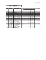
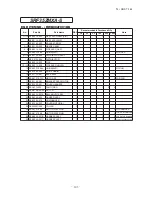
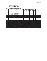
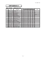
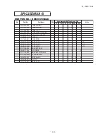
SRF25ZMXA-S
END ITEM NO. : RWB002F001BA
Recommendable Purchased Q'ty
10
30
50
100
500 1000
1
㹼
7 RFB 501A 002H CONTROL UNIT
1
1 RKY 505A 001MF PWB ASSY
1
2
2
4
8
2 SSA 561B 702B BLOCK,TERMINAL
1
1
1
2
2 T1
3 SSA 554D 183
KILLER,NOISE
1
4 SSA 551A 223C SENSOR ASSY
1
1
1
2
4
INCL.SENSOR
(ROOM TEMP.& HEAT EXCH.1,2)
5 SSA 551B 017B SENSOR(HUMIDITY)
1
1
1
2
4
6 RFB 504A 003
HARNESS ASSY(DAMP)
1
1
1
1
2
7 RFB 504A 004
HARNESS ASSY(FLAP)
1
1
1
1
2
8 RFB 503A 001
DISPLAY ASSY
1
1
1
2
4
9 RFB 505A 001
PWB ASSY(DISPLAY)
1
2
2
4
8
10 PSA 941F 001
SPRING,LEAF
2
11 RFB 008A 001D PARTS,STANDARD
1
12 RLA 502A 700C CONTROL ASSY,REMOTE
1
2
3
5
10
13 RFB 012A 006B
MANUAL,INSTRUCTION
1
14 RKT 437A 005
FILTER,LIGHT CLEAN
1
15 RKT 437A 011
FILTER,CLEAN
1
16 RLA 032A 700
HOLDER(REMO-CON)
1
1
1
1
2
(17) RFB 011F 001N LABEL,MODEL NAME
1
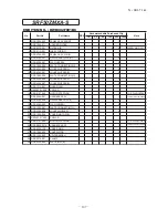
No.
Part No.
Part Name
RE.Q
Note
Содержание SRF25ZMXA-S
Страница 2: ......
Страница 3: ... 14 SRF T 163 TECHNICAL MANUAL ...
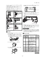
Страница 12: ... 10 14 SRF T 163 3 Remote control Unit mm 60 26 167 a Wireless remote control ...
Страница 93: ... 91 14 SRF T 163 WARING CAUTION 3 Super link E board SC ADNA E F ...
Страница 94: ... 92 14 SRF T 163 ...
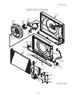
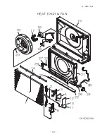
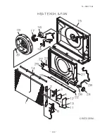
Страница 98: ... 96 14 SRF T 163 CRCE0008A 12 1 9 10 4 3 19 22 26 24 20 18 23 25 21 6 2 11 5 13 14 16 17 15 HEAT EXCH FAN ...
Страница 100: ... 98 14 SRF T 163 CRCE0010 12 13 14 3 2 1 4 4 5 10 10 4 7 8 9 6 15 16 11 CONTROL PARTS SET ...
Страница 104: ... 102 14 SRF T 163 CRCE0009A 15 1 2 22 25 29 14 27 23 21 26 28 24 11 12 13 3 4 5 6 16 17 19 20 18 HEAT EXCH FAN ...
Страница 106: ... 104 14 SRF T 163 CRCE0010 12 13 14 3 2 1 4 4 5 10 10 4 7 8 9 6 15 16 11 CONTROL PARTS SET ...
Страница 110: ... 108 14 SRF T 163 CRCE0009A 15 1 2 22 25 29 14 27 23 21 26 28 24 11 12 13 3 4 5 6 16 17 19 20 18 HEAT EXCH FAN ...
Страница 112: ... 110 14 SRF T 163 CRCE0010 12 13 14 3 2 1 4 4 5 10 10 4 7 8 9 6 15 16 11 CONTROL PARTS SET ...
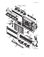
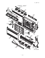
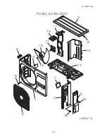
Страница 114: ... 112 14 SRF T 163 CRBE0276 6 13 11 12 15 16 3 17 14 2 4 9 8 7 5 1 8 8 10 PANEL FAN ASSY ...
Страница 118: ... 116 14 SRF T 163 CRBE0276 6 13 11 12 15 16 3 17 14 2 4 9 8 7 5 1 8 8 10 PANEL FAN ASSY ...
Страница 122: ... 120 14 SRF T 163 CRBE0315 9 13 15 16 14 17 7 6 4 1 8 3 11 5 18 10 10 10 2 12 PANEL FAN ASSY ...


