


Page 32
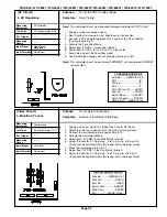
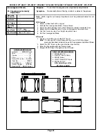
Purpose:
Measuring
Instrument
Test Point
Measuring
Range
Input Signal
Ext. Trigger
Input Terminal
Symptom:
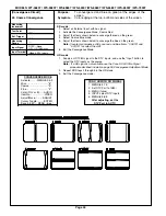
Purpose
Measuring
Instrument
Test Point
Measuring
Range
Input Signal
Ext. Trigger
Input Terminal
Symptom:
MODELS: WT-46807 / WS-55807 / WS-55857 / WS-55907 /WS-65807 / WS-65857 / WS-65907 / WS-73907
Oscilloscope
Connector JA pins 6 & 8
------
50mV/Div
RF Stereo
300 Hz modulation
RF Input
Check the input signal level to the MCS circuit
Distorted sound during a stereo broadcast.
1. Supply an RF MCS signal to the Ant A input, 300 Hz at 100% modulation
(25 kHz deviation) for right and left channels.
2. Connect the oscilloscope to connector JA pin 8 (Main Tuner Right Audio).
3. Enter the Adjustment Mode and select the Audio Function.
4. Verify that the Audio Function items are set to the data values given the
table below.
5. Set the data for Item “1 INP” for 1.56 Vp-p ±0.06V.
6. Connect the oscilloscope to connector JA pin 6 (Main Tuner Left Audio).
7. Confirm that the left audio level at pin 6 of the JA connector is 1.56 Vp-p
±0.06V.
Note:
Adjustment 2 (Stereo Separation) must be performed after this adjustment)
[Audio Circuit]
1. MCS Input Level
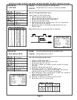
Oscilloscope
Conector JA pin 8
------
10mV/Div
RF Stereo
RF Input
[Audio Circuit]
2. Separation
Check stereo separation
Poor stereo separation
Note:
This adjustment must follow Adjustment 1 (Input Level)
1. Supply a RF Stereo Signal (dual tone stereo) to the Ant. A input.
• Left Channel = 300 Hz modulation
• Right Channel = no modulation
2. Connect the oscilloscope to connector JA pin 8 (Main Tuner Right Audio).
3. Enter the Adjustment Mode and select the Audio Function.
4. Set the data for Item “3 WDE” for minimum Right Audio signal.
5. Change the modulation frequency to 3kHz.
6. Adjust the data for Item “4 SPC” for minimum Right Audio signal.
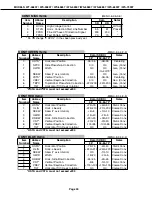
AUDIO Function
Item #
Abbrev.
Data
1
INP
7
3
WDE
16
4
SPC
16
CIRCUIT ADJUST MODE
Activate …….. MENU-8-2-5-7
Function …...………..AUDIO
Item No. ……….…….VIDEO
Adjust Data ….…….ADJUST
Save Data …. ………ENTER
Exit …………..MENU (twice)
CIRCUIT ADJUST MODE
Activate …….. MENU-8-2-5-7
Function …...………..AUDIO
Item No. ……….…….VIDEO
Adjust Data ….…….ADJUST
Save Data …. ………ENTER
Exit …………..MENU (twice)
Содержание WS-55807
Страница 2: ......
Страница 69: ...MODELS WT 46807 WS 55807 WS 55857 WS 55907 WS 65807 WS 65857 WS 65907 WS 73907 Page 69 PCB SIGNAL Y C PATH ...
Страница 70: ...MODELS WT 46807 WS 55807 WS 55857 WS 55907 WS 65807 WS 65857 WS 65907 WS 73907 Page 70 SYNC PATH ...
Страница 72: ...MODELS WT 46807 WS 55807 WS 55857 WS 55907 WS 65807 WS 65857 WS 65907 WS 73907 Page 72 SOUND CIRCUIT ...
Страница 73: ...MODELS WT 46807 WS 55807 WS 55857 WS 55907 WS 65807 WS 65857 WS 65907 WS 73907 Page 73 CONVERGENCE CIRCUIT ...
Страница 74: ...MODELS WT 46807 WS 55807 WS 55857 WS 55907 WS 65807 WS 65857 WS 65907 WS 73907 Page 74 CONTROL CIRCUIT ...
Страница 75: ......
Страница 76: ......
Страница 77: ......
Страница 78: ......
Страница 79: ......
Страница 80: ......
Страница 81: ......
Страница 82: ......
Страница 83: ......
Страница 85: ......
Страница 86: ......
Страница 87: ......
Страница 88: ......
Страница 89: ......
Страница 90: ......
Страница 91: ......
Страница 92: ......
Страница 93: ......
Страница 94: ......
Страница 95: ......
Страница 96: ......
Страница 97: ......
Страница 98: ......
Страница 99: ......