24
25
See Appendix B for component video
signal compatibility information.
For digital audio connections, see your
DVD Owner’s Guides.
IMPORTANT
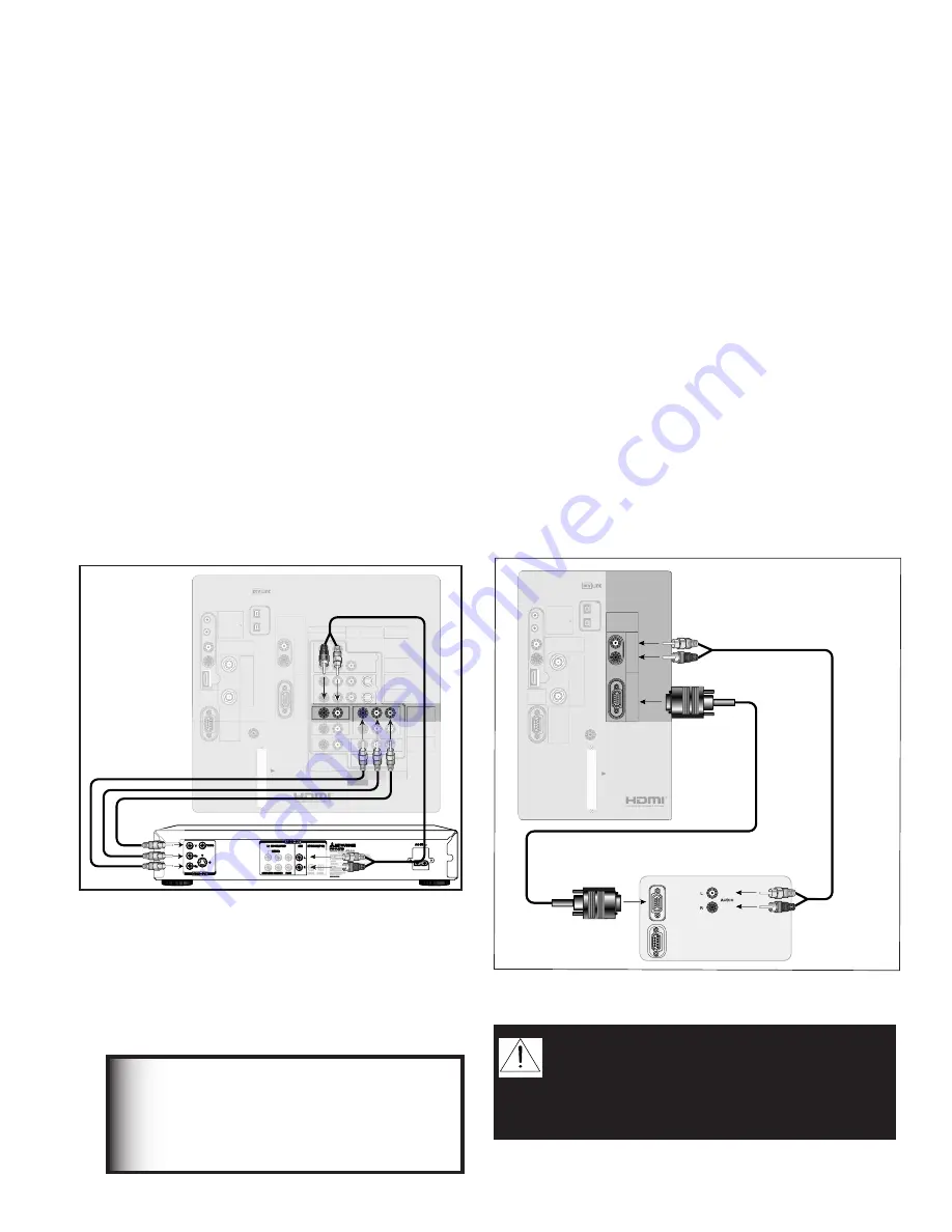
Connecting a DVD Player with Component Video or
Computer with a PC Monitor Output
DVD Player with Component Video
Figure 9
Component video cables and audio cables are required.
These are not included with the TV.
1. Connect the Component Video cables from Y/Pr/
Pb VIDEO OUT on the back of the DVD player to
COMPONENT-1 on the TV back panel, matching
the correct connection:
•
Y
to Y (Green)
•
Pr
to Pr (Red)
•
Pb
to Pb (Blue)
2. Connect a set of audio cables from AUDIO OUT
on the back of the DVD player to COMPONENT-1
AUDIO Input on the TV back panel. The red cable
connects to the R (right) channel, and the white
cable connects to the L (left) channel.
IR EMITTER
NetCommand
R
DVI
Analog Audio
INPUT-1
AUDIO 2
AUDIO/VIDEO 1
AUDIO
L(MONO)
INPUT-2
COMPONENT-1
YPbPr (480i/480p/720p/1080i)
Y/G
Pb/B
Pr/R
COMPONENT-2
YPbPr (480i/480p/720p/1080i)
INPUT-DTV
YPbPr / RGB HV
(480i/480p/720p/1080i)
DTV/
CABLE/
VHF/
UHF
ANT-2
ANT-1
DIGITAL
AUDIO
PC
VGA/SVGA/XGA/
720p
60 Hz
PC-
AUDIO
PC-
INPUT
M-LINK
CONTROL/
RS-232C
HDMI
M-LINK
IEEE1394
INPUT/OUTPUT
L
R
VIDEO
S-VIDEO
MONITOR
OUTPUT
L
R
V
H
CARD
TOP
C
ab
leC
AR
D
SL
O
T
TM
MAIN
AUX
VIDEO
S
Y
C
B
C
R
VIDEO OUT
BITSTREAM/PCM
5.1 CH SURROUND
2CH
L
R
CENTER
SUBWOOFER SURROUND
FRONT
COAXIAL OPTICAL
AUDIO OUT
AC IN
MITSUBISHI
DVD PLAYER
MODEL
DD-5000
POWER SUPPLY
120V~ 60Hz
POWER CONSUMPTION
20W
MITSUBISHI DIGITAL ELECTRONICS
DISTRIBUTED BY
9351 JERONIMO ROAD
IRVINE, CA 92618
MADE IN JAPAN
AMERICA, INC.
SERIAL NO.
MANUFACTURED
Red
DVD back panel
TV back panel
White
Red
1.
2.
R
Red
1.
2.
White
1.
Note:
NetCommand® will assume you
connected your DVD player to Component-1. If
you add a second DVD or use any other inputs
for your DVD, this change must match in the
NetCommand system. See
Edit NetCommand...
in Chapter 3 for more information.
Figure 9. Connecting a DVD Player with Component
Video
TV back panel (section detail)
IR EMITTER
NetCommand
R
DTV/
CABLE/
VHF/
UHF
ANT-2
AUX
ANT-1
MAIN
DIGITAL
AUDIO
PC
VGA/SVGA/XGA/
720p
60 Hz
PC-
AUDIO
PC-
INPUT
M-LINK
CONTROL/
RS-232C
HDMI
M-LINK
IEEE1394
INPUT/OUTPUT
L
R
CARD
TOP
C
ab
leC
AR
D
SL
O
T
TM
Computer with Monitor Output
L
R
Analog Audio
DVI
Computer with a PC Monitor Output
Figure 10
1. Connect PC Monitor Out from the computer to PC
Input on the TV back panel using a PC compatible
monitor cable. See Appendix B for PC signal
compatibility.
2. Connect the L (left) and R (right) audio cables from
the computer to PC AUDIO on the TV back panel. If
the computer’s audio output is a single mini-jack,
a mini audio to RCA male “Y” adaptor cable is
needed to complete this connection.
Note:
To utilize the benefits of a digital A/V
receiver, connect your computer’s digital audio
out, if available, to a digital input on your digital
A/V receiver.
Figure 10. Connecting a Computer with a PC Monitor
CAUTION:
To ensure continued FCC
compliance, the user must use a shielded
video interface cable with bonded ferrite
cores at both ends when using the PC
input.
Содержание WD-52825
Страница 16: ...16 ...
Страница 80: ...80 ...
Страница 88: ...88 This page intentionally blank ...
Страница 98: ...98 Appendix H Filter Cleaning ...


