


V20 Chassis Technical Training
and Troubleshooting Guide
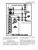
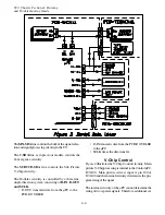
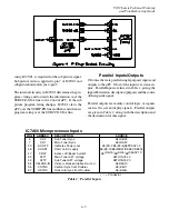
5-2
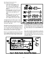
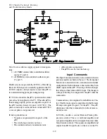
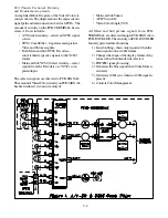
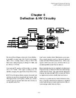
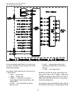
A simplified Block Diagram of the Video/Color cir-
cuitry is shown. The diagram shows the major circuits,
signal path and interconnections between PCBs. The
amount of circuitry on the PCB-TERMINAL has in-
creased. It now includes:
• A/V Switch circuitry – selects an NTSC signal
source.
• 3DYC Comb Filter – Separates main picture
Video and Chroma signals.
• Both Main and Sub NTSC Decoders –
convert their respective signals to the YCbCr
format.
• Main and Sub YCbCr Select circuitry – select
signals from the Decoders or a YCbCr com-
ponent input.
The selected signals are directed to PCB-SIGNAL.
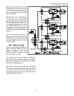
The amount of Video/Color circuitry on PCB-SIGNAL
has been reduced, it consists mainly of:
• Main and Sub Tuners
• A PIP Switch IC
• Video Color Jungle (VCJ).
All Main and Sub picture signals from PCB-
TERMINAL are directed though PCB-SIGNAL to
PCB-DOUBLER. The circuitry on PCB-DOUBLER
basically performs three functions:
1) Line doubling – this is only required when the
main signal source is 480i format.
2) Changes the shape of the display format if any
format other than Standard is selected.
3) POP/PIP signal processing.
4) Generates the blue signal when Video Mute is
activated.
5) Generates 1080i sync when no 1080i signal is
present
6) Controls Color Management.
Содержание VS-50111
Страница 2: ...x ...
Страница 4: ...x ...
Страница 6: ...V20 Chassis Technical Training and Troubleshooting Guide ii ...
Страница 10: ...V20 Chassis Technical Training and Troubleshooting Guide 1 4 ...
Страница 20: ...V20 Chassis Technical Training and Troubleshooting Guide 2 10 ...
Страница 38: ...V20 Chassis Technical Training and Troubleshooting Guide 5 6 ...