2-14
Installation
2Unpacking to Installation
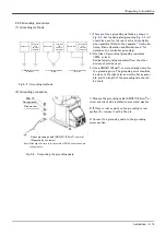
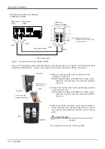
2.2.5 Connecting with the controller
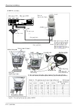
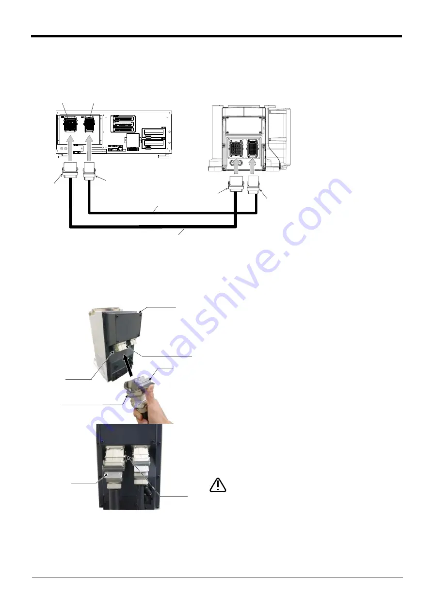
(1) CR750 controller
Fig.2-7 : Connecting the machine cables (CR750)
Carry out the following procedure after installing the controller referring to the separate "Controller Setup, Basic
Operation and Maintenance" manual. The procedure of connecting the machine cable is shown below.
1) Make sure that the power switch on the front of the
controller is turned OFF.
Note) Although the figure is RH-6FH, also in other robots
with same connector type, the connection method is
the same.
2) Connect the machine cable to its corresponding connector
on the robot arm side.
Note) Although the figure is RH-6FH, also in other robots
with same connector type, the connection method is
the same.
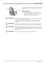
3) After connecting the connector, insert the hook attached
to the connector on the machine cable side to the rear of
the projection of the robot arm connector to fix securely in
place.
This complete the connection of machine cable.
CN1
CN2
ロボット本体
(ベース部背面)
ラッチ
ラッチ
モータ信号ケーブル
モータパワーケーブル
モータパワー
(CN1)
モータ信号
(CN2)
ラッチ
ラッチ
CN1
CN2
Motor power
(CN1)
Motor signal
(CN2)
Latch
Latch
Motor signal cable
Motor power cable
Latch
Latch
Robot arm
(Rear of the base.)
Note) Although the figure is the
example of RV-4F other types
are the same also.
固定フック
機器間ケーブル側コネクタ
ロボット本体
ロボット本体側コネクタ
突起部
Robot arm
Connector on the
robot arm side
Hook
Projection
Connector on the
machine cable side
固定フック
突起部
Hook
Projection
CAUTION
Be careful not to get your hand
pinched.
Содержание RV-13FM-SE Series
Страница 2: ......
Страница 138: ...Appendix 128 Configuration flag 6Appendix ...
Страница 139: ......


