8
CC IE Control UTILITY
8
- 34
8.5 Diagnostics Screen
8.5.1 CC-Link IE Controller Network diagnostics result screen
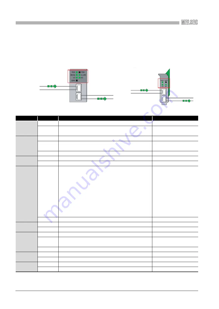
(5) Select station network device status LED display
Displays the LED status on the top part of the CC-Link IE Controller Network module
and CC-Link IE Controller Network board according to the device status in the "Select
station network device status display" field.
*1: Displayed only when the target module or board is equipped with a external power supply.
For modules
For boards
Name
LED status
For modules
For boards
RUN
ON, green
Operating normally
Operating normally
OFF
Hardware error or watchdog timer error
WDT error occurred, or board
resetting
MODE
ON, green
Online mode
—
Flashing,
green
Test mode
—
OFF
Offline mode
—
SD
ON, green
Sending data
Sending data
OFF
Not sending data
Not sending data
ERR.
ON, red
• Received data is a fault. (Receive frame error)
• A frame error over the certain level occurred in between
stations.
• Control stations or station numbers are overlapped.
• Cable disconnection, incorrect cable connection between IN
and OUT.
• Network parameters are corrupted , or some settings are
inconsistent between the control and normal stations. (Such
as reserved station specification, total station numbers, and
network numbers)
Error occurred
OFF
Normal status
Normal status
PRM
ON, green
Operating as a control station.
—
OFF
Operating as a normal station.
—
D.LINK
ON, green
Operating data link (cyclic transmission operated)
—
Flashing,
green
Operating data link (cyclic transmission stopped)
—
OFF
Not operating data link (Disconnected from network)
—
RD
ON, green
Receiving data
Receiving data
OFF
Not receiving data
Not receiving data
EXT.PW
*1
ON, green
External power supplied
External power supplied
OFF
External power not supplied
External power not supplied


