


13
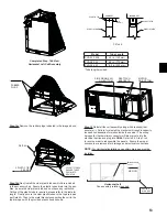
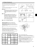
Step.14d
Next, install the clear plastic tubes which are included
in the accessory bag. Ensure the plastic tubes drain into the pan.
Also, be sure the clear plastic tubes do not have any restriction.
Cutting of the plastic tube is required, please refer to the table for
length. Finally, secure the clear plastic tubes to the top drain pan
per Detail A. Then to the metal brackets supporting the coil to the
top drain pan with the provided plastic ties as shown.
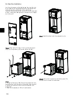
Step.15
Reinstall the coil assembly along with bracket(s) that
secure(s) it. Failure to reinstall the brackets will result in capacity
loss and condensation formation inside the cabinet. The wiring
harness for the thermistor connector will also reroute into the
electrical section and plug into
CN44
. Refer to 9.3. Step 1 to 4
in reverse order to reassemble the panels. Ensure the proper
knockouts are removed for drainage and electrical connections.
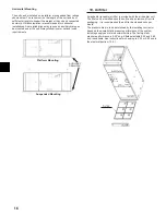
NOTE:
For Horizontal installation an auxiliary drain pan must be
installed.
Auxiliary
drain pan
MOTOR
ON BOTTOM
SIDE DRAIN PAN
ON BOTTOM
REATTACH
BRACKETS
PRIMARY DRAIN
3/4
”
FPT
2 PLASTIC TIES
PER SIDE
2 PLASTIC TUBES
ENSURE TUBES
DRAIN INTO
DRAIN PAN
AIRFLOW
Horizontal Left
Fan assembly rotation required
DETAIL A
Model
Tube Length
PVA-A12, A18
4.9 in. (125 mm)
PVA-A24, 30
6.9 in. (175 mm)
PVA-A36, 42
*8.9 in. (225 mm)
*Tube length provided.
5/8”
(15mm)
PLASTIC TIE
PLASTIC TUBE
PLASTIC TIE
PLASTIC TUBE
CORRECT
INCORRECT
DETAIL A
Completed Step. 14b View
Horizontal Left Coil Assembly
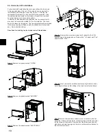
Step.14c
Remove the rubber plugs indicated in the image above.
RUBBER
PLUGS
Содержание PVA-A12AA7
Страница 57: ...57 ...


