Mitsubishi Electric PUZ-WM112VAA Скачать руководство пользователя страница 1

SERVICE MANUAL

No. OCH727

R32

March 2020

PARTS CATALOG (OCB727)
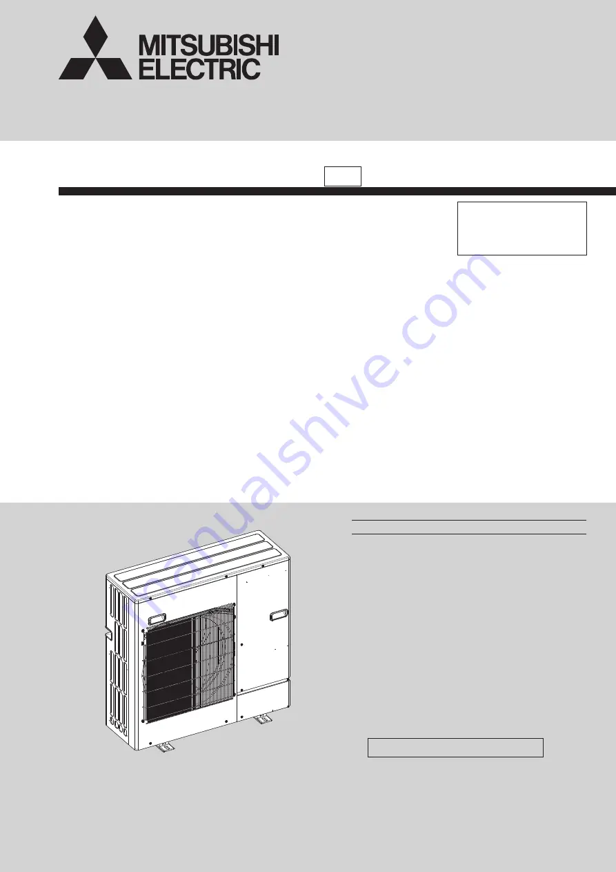
<Outdoor unit>

[Model Name]

PUZ-WM50VHA

PUZ-WM60VAA

PUZ-WM85VAA

PUZ-WM85YAA

PUZ-WM112VAA

PUZ-WM112YAA

Salt proof model 

PUZ-WM50VHA-BS

PUZ-WM60VAA-BS

PUZ-WM85VAA-BS

PUZ-WM85YAA-BS

PUZ-WM112VAA-BS

PUZ-WM112YAA-BS

CONTENTS

1. REFERENCE MANUAL ································ 2
2. SAFETY PRECAUTION ······························· 3

3. SPECIFICATIONS ······································ 10

4. DATA ··························································· 12

5. OUTLINES AND DIMENSIONS·················· 13

6. WIRING DIAGRAM ····································· 15

7. WIRING SPECIFICATIONS ························ 18

8. REFRIGERANT SYSTEM DIAGRAM ········ 19

9. TROUBLESHOOTING ································ 22

10. MONITORING THE OPERATION DATA BY THE REMOTE CONTROLLER ···· 60

11. DISASSEMBLY PROCEDURE ··················· 66

Note:

• This manual describes 

service data of the outdoor 

units only.

AIR TO WATER HEAT PUMP UNITS 

[Service Ref.]

PUZ-WM50VHA.UK

PUZ-WM60VAA.UK

PUZ-WM85VAA.UK

PUZ-WM85YAA.UK

PUZ-WM112VAA.UK

PUZ-WM112YAA.UK

PUZ-WM50VHA-BS.UK

PUZ-WM60VAA-BS.UK

PUZ-WM85VAA-BS.UK

PUZ-WM85YAA-BS.UK

PUZ-WM112VAA-BS.UK

PUZ-WM112YAA-BS.UK

PUZ-WM50VHA.UK

Содержание PUZ-WM112VAA

Страница 1: ...TA 12 5 OUTLINES AND DIMENSIONS 13 6 WIRING DIAGRAM 15 7 WIRING SPECIFICATIONS 18 8 REFRIGERANT SYSTEM DIAGRAM 19 9 TROUBLESHOOTING 22 10 MONITORING THE OPERATION DATABY THE REMOTE CONTROLLER 60 11 DISASSEMBLY PROCEDURE 66 Note This manual describes service data of the outdoor units only AIR TO WATER HEAT PUMP UNITS Service Ref PUZ WM50VHA UK PUZ WM60VAA UK PUZ WM85VAA UK PUZ WM85YAA UK PUZ WM112V...

Страница 2: ...20X VM6D EHPT30X MED EHPT30X YM9ED ERPT30X VM2ED EHPT17X VM2D UK EHPT17X VM6D UK EHPT17X YM9D UK ERPT17X VM2D UK EHPT20X MED UK EHPT20X VM6D UK EHPT20X YM9D UK EHPT20X YM9ED UK EHPT20X TM9D UK EHPT20X MHEDW UK ERPT20X MD UK ERPT20X VM2D UK ERPT20X VM6D UK EHPT30X MED UK EHPT30X YM9ED UK ERPT30X VM2ED UK OCH714 OCB714 EHPX VM2D EHPX VM6D EHPX YM9D EHPX MED EHPX YM9ED EHPX VM2D UK EHPX VM6D UK EHPX ...

Страница 3: ...ant Do not touch the hot or cold areas in the refrigerating cycle When the repair or the inspection of the circuit needs to be done without turning off the power exercise great caution not to touch the live parts Use a vacuum pump with a reverse flow check valve Vacuum pump oil may flow back into refrigerant cycle and that can cause deterioration of refrigerant oil etc Use the following tools spec...

Страница 4: ...friger ant leaks before performing the work If refrigerant leaks and accumulates it may ignite or poisonous gases may be released 11 Do not install the unit in places where refrigerant may build up or places with poor ventilation such as a semi base ment Refrigerant is heavier than air and inclined to fall away from the leak source 12 The appliance shall be stored in a room without continuously op...

Страница 5: ...ents are being changed they shall be fit for the purpose and to the correct specification At all times the manufacturer s maintenance and service guidelines shall be followed If in doubt consult the manufacturer s technical department for assistance The following checks shall be applied to installations using flammable refrigerants The charge size is in accordance with the room size within which t...

Страница 6: ...e conventional procedures shall be used However for flammable refrigerants it is important that best practice is followed since flammability is a considera tion The following procedure shall be adhered to remove refrigerant purge the circuit with inert gas evacuate purge again with inert gas open the circuit by cutting or brazing The refrigerant charge shall be recovered into the correct recovery ...

Страница 7: ...off valves in good working order Empty recovery cylinders are evacuated and if possible cooled before recovery occurs The recovery equipment shall be in good working order with a set of instructions concerning the equipment that is at hand and shall be suitable for the recovery of all appropriate refrigerants including when applicable flammable refriger ants In addition a set of calibrated weighin...

Страница 8: ... other refrigerants can be used 2 3 PRECAUTIONS WHEN REUSING EXISTING R22 R410a REFRIGERANT TOOLS Cautions for refrigerant piping work Although BS model has been designed to be resistant to salt damage observe the following precautions to maintain the performance of the unit 1 Avoid installing the unit in a location where it will be exposed directly to seawater or sea breeze 2 If the cover panel m...

Страница 9: ...ded refrigerant B Install in a space with a depression height of 0 125 m C Create an appropriate ventilation open area Make sure that the width of the open area is 0 9 m or more and the height of the open area is 0 15 m or more However the height from the bottom of the installation space to the bottom edge of the open area should be 0 125 m or less Open area should be 75 or more opening Amin Heigh...

Страница 10: ... 37 3 8 1050 41 5 16 D mm inch 330 30 2 13 1 3 16 480 18 7 8 H mm inch 943 37 1 8 1020 40 3 16 Weight kg lb 71 157 97 214 98 216 111 245 Refrigerant R32 Charge kg lb 2 0 4 4 2 2 4 9 Oil Model L 0 60 FW68S 0 60 FW68S Water pipe connection G1B WATER 1 Hot gas with 4 way valve 2 Grill Service Ref PUZ WM112VAA UK PUZ WM112VAA BS UK PUZ WM112YAA UK PUZ WM112YAA BS UK OUTDOOR UNIT Power source Phase cyc...

Страница 11: ... return water temperature due to the water quantity of system Available range 10L 15L Available range 7L 12L Available range Available range 7L 12L 15L 25L 12L 17L 25L 40L 17L 22L 12L 17L over 40L over 22L over 17L Unavailable range Unavailable range Unavailable range Unavailable range 12 0 16 0 20 0 24 0 28 0 32 0 36 0 40 0 11 0 14 0 17 0 20 0 23 0 26 0 5 0 9 0 7 0 11 0 13 0 15 0 17 0 14 19 24 29...

Страница 12: ... 1000 2000 4000 8000 APPROXIMATE THRESHOLD OF HEARING FOR CONTINUOUS NOISE BAND CENTER FREQUENCIES Hz COOLING MODE HEATING 45 SPL dB 45 LINE 1 5 m 1 m MICROPHONE UNIT GROUND PUZ WM112VAA UK PUZ WM112VAA BS UK PUZ WM112YAA UK PUZ WM112YAA BS UK PUZ WM50VHA UK PUZ WM50VHA BS UK PUZ WM60VAA UK PUZ WM60VAA BS UK PUZ WM85VAA UK PUZ WM85VAA BS UK PUZ WM85YAA UK PUZ WM85YAA BS UK NC 60 NC 50 NC 40 NC 30 ...

Страница 13: ... 5 ISO 228 1 G1 B 98 269 24 REAR AIR INTAKE SIDE AIR INTAKE 2XU SHAPED NOTCH HOLES FOUNDATION BOLT M10 2 12 36 OVAL HOLES FOUNDATION BOLT M10 INSTALLATION FEET AIR DISCHARGE 370 53 28 417 19 175 600 175 330 30 2 185 DRAIN HOLE 5 Ø33 145 145 145 220 30 219 81 HANDLE FOR MOVING AIR INTAKE WATER OUT WATER IN HANDLE FOR MOVING REAR AIR INTAKE 57 HANDLE FOR MOVING SIDE AIR INTAKE SEE DETAIL FRONT COVER...

Страница 14: ...43 116 200 120 OVER50mm OVER15mm O V ER 3 0 0 m m FREE O V ER 1 0 0 0 m m SERVICE SPACE OVER OVER OVER OVER OVER 300 500 50 500 15 LESS THAN 30 INDICATION OF PRESSURE RELIEF VALVE DRAIN PORT ONLY FOR PUZ WM SERIES 2 EXAMPLE OF NOTE 1 INDICATION OF TERMINAL CONNECTION LOCATION FOUNDATION BOLT HEIGHT THE DIAGRAM BELOW SHOWS A BASIC EXAMPLE EXPLANATION OF PARTICULAR DETAILS ARE GIVEN IN THE INSTALLAT...

Страница 15: ...15 OCH727 6 WIRING DIAGRAM PUZ WM50VHA UK PUZ WM50VHA BS UK ...

Страница 16: ...16 OCH727 PUZ WM60VAA UK PUZ WM85VAA UK PUZ WM112VAA UK PUZ WM60VAA BS UK PUZ WM85VAA BS UK PUZ WM112VAA BS UK ...

Страница 17: ...17 OCH727 PUZ WM85YAA UK PUZ WM112YAA UK PUZ WM85YAA BS UK PUZ WM112YAA BS UK ...

Страница 18: ...the S3 terminal caused by electrical circuit design that has no electrical insulation between power line and communication signal line Therefore please turn off the main power supply when servicing And do not touch the S1 S2 S3 terminals when the power is energized If isolator should be used between indoor unit and outdoor unit please use 3 pole type Caution Be sure to install N line Without N lin...

Страница 19: ...sure P B Power circuit board Inverter power board LEV A Linear expansion valve A Heating Secondary LEV Cooling Primary LEV LEV B Linear expansion valve B Heating Primary LEV Cooling Secondary LEV TH3 Liquid temperature thermistor Heating Evaporating temperature Cooling Sub cool liquid temperature TH4 Discharge temperature thermistor For LEV control and for compressor protection TH6 2 phase pipe te...

Страница 20: ...ture thermistor Heating Evaporating temperature Cooling Condensing temperature TH7 Ambient temperature thermistor For fan control and for compressor frequency control TH8 Heat sink temperature thermistor For power board protection TH33 Comp surface temperature thermistor For protection TH34 Plate HEX liquid temperature thermistor Heating Sub cool liquid temperature Cooling Evaporating temperature ...

Страница 21: ...re from refrigerant pressure LEV A Linear expansion valve A Heating Secondary LEV Cooling Primary LEV LEV B Linear expansion valve B Heating Primary LEV Cooling Secondary LEV TH3 Liquid temperature thermistor Heating Evaporating temperature Cooling Sub cool liquid temperature TH4 Discharge temperature thermistor For LEV control and for compressor protection TH6 2 phase pipe temperature thermistor ...

Страница 22: ...se of the trouble according to 9 3 TROUBLESHOOTING OF PROBLEMS The trouble is not reoccurring Logged 1Consider the temporary defects such as the work of protection devices in the refrigerant circuit including compressor poor connection of wiring noise etc Re check the symptom and check the installation environment refrigerant amount weather when the trouble occurred matters related to wiring etc 2...

Страница 23: ...nal on outdoor power circuit board Check connection of the connector LI or NI Refer to 9 6 TEST POINT DIAGRAM 3 Check connection of the connector CNDC on the outdoor controller circuit board Check connection of the connector CNDC on the outdoor power circuit board V the noise filter Y Refer to 9 6 TEST POINT DIAGRAM 4 Check connection of reactor DCL or ACL Refer to 9 6 TEST POINT DIAGRAM 5 a Check...

Страница 24: ...rd indoor controller board or indoor power board if abnormality occurs again 7 Check if refrigerant addresses SW1 3 to SW1 6 on outdoor controller circuit board are overlapping in case of multiple outdoor units control 8 Check transmission path and remove the cause Note The descriptions above 1 8 are for EA Eb and EC Eb 6845 Miswiring of indoor outdoor unit connecting wire reverse wiring or discon...

Страница 25: ...High comp surface temperature Abnormal if TH33 exceeds 125 In the case of high comp surface temperature error compressor does not restart unless the thermistor TH33 becomes less than 95 TH33 Thermistor Comp surface 1 Overheated compressor operation caused by shortage of refrigerant 2 Defective operation of stop valve 3 Defective thermistor 4 Defective outdoor controller board 5 Defective action of...

Страница 26: ...place outdoor power circuit board 7 Replace outdoor controller circuit board U6 4250 Power module Check abnormality by driving power module in case overcurrent is detected UF or UP error condition 1 Outdoor stop valve is closed 2 Decrease of power supply voltage 3 Looseness disconnection or reverse of compressor wiring connection 4 Defective compressor 5 Defective outdoor power circuit board 1 Ope...

Страница 27: ...onverter circuit board WM85Y WM112Y 5 Check RS wiring WM85Y WM112Y 6 Replace RS WM85Y WM112Y 7 Check CN2 wiring WM50V WM60V WM85V WM112V 8 Replace outdoor controller circuit board WM50V WM60V WM85V WM112V 04 Input current sensor error L1 phase open error Decrease in input current through outdoor unit to 0 1A only if operation frequency is more than or equal to 40Hz or compressor current is more th...

Страница 28: ...roller board 1 Check outdoor unit air passage 23 Turn the power off and on again to check the check code If U4 is displayed follow the U4 processing direction UE 1509 Abnormal pressure of 63HS Abnormal if 63HS detects 0 1 MPa or less Detection is inoperative for 3 minutes after compressor starting and 3 minutes after and during defrosting 63HS Pressure sensor 1 Disconnection or contact failure of ...

Страница 29: ... V W during test run No defect on board if voltage among phases U V V W and W U is same Make sure to perform the voltage check with same performing frequency 7 Check compressor Refer to 9 4 HOW TO CHECK THE PARTS 8 Replace outdoor power circuit board 9 Check the DIP switch setting of outdoor controller circuit board E0 or E4 6831 or 6834 Remote controller transmission error E0 signal receiving err...

Страница 30: ...mmunication circuit of indoor controller board 4 Noise has entered into indoor outdoor unit connecting wire 1 Check disconnection or looseness of indoor outdoor unit connecting wire of indoor or outdoor units 2 4 Turn the power off and on again to check Replace indoor controller board or outdoor controller circuit board if abnormality is displayed again E9 6841 Indoor outdoor unit communication er...

Страница 31: ...s 10 seconds smaller than the threshold The threshold is dynamically calculated by inner operation using the operating time of the compressor and the water tem perature 1 Freezing protection Cooling mode 1 Reduced water flow Clogged filter Leakage of water 2 Low temperature Low load Inlet water is too cold 3 Defective water pump 4 Defective outdoor fan control 5 Leakage or shortage of refrigerant ...

Страница 32: ...play is appeared but it will be turned off soon 1 After cancelling to select function from the remote controller the remote controller opera tion switch will be not accepted for approx 30 seconds 1 Normal operation 4 Remote controller display works normally and the unit performs cooling operation however the capacity cannot be fully obtained 1 Refrigerant shortage 2 Filter clogging 1 If refrigeran...

Страница 33: ...ter is dripping or vapour is emitted from the outdoor unit During cooling mode water may form and drip from the cool pipes and joints During heating mode water may form and drip from the heat exchanger of outdoor unit During defrosting mode water on the heat exchanger of outdoor unit evapo rates and water vapour may be emitted When restarting the outdoor unit soon after stopping it it does not ope...

Страница 34: ...agnosis after turning on the main power Normal The startup diagnosis will be over in around 2 minutes Miswiring of indoor outdoor connecting wire Breaking of indoor outdoor connecting wire S3 Defective indoor controller board Defective outdoor controller circuit board Refer to Self diagnosis action table in order to solve the trouble In case of communication errors the display of remote controller...

Страница 35: ... outdoor unit Check if the wiring is bad Check if the fuses are blown The fuses on the outdoor controller circuit board will be blown when the indoor outdoor connecting wire short circuits Bad wiring of the outdoor controller board The fuses on the outdoor controller circuit board are blown Check if miswiring breaking or poor contact is causing this problem Indoor outdoor connecting wire is polari...

Страница 36: ...or controller circuit board Replace the outdoor controller circuit board Normal Only the unit which has the refrigerant address 0 supplies power to the remote controller Set the refrigerant address to 0 In case of the multiple outdoor units control recheck the refrigerant address again Defective indoor power board Replace the indoor power board Defective outdoor power circuit board Replace the out...

Страница 37: ...r poor contact of the remote controller wire Check the voltage of the remote controller wire If it is not between 10 and 16 V DC the indoor controller board must be defective The remote controller wire short circuits Check if the remote controller wire is short circuited Defective indoor controller board Replace the indoor controller board Diagnosis flow Cause Inspection method and troubleshooting...

Страница 38: ...for compressor MC Linear expansion valve LEV A LEV B Normal Abnormal Open or short Disconnect the connector then measure the resistance with a tester Winding temperature 20 Normal Gray Black Gray Red Gray Yellow Gray Orange Abnormal 46 3 Open or short Refer to the next page Fan motor MF1 Measure the resistance between the terminals with a tester Winding temperature 20 W V U 1435 i 150 160 to 410 k...

Страница 39: ...0 V DC TEST POINT 2 VCC between 5 and 4 of the fan connector VCC 15 V DC Replace the defective fan motor Replace the outdoor controller board Replace the defective fan motor Replace the outdoor controller board C B and the defective fan motor MF1 Replace outdoor controller board Replace the defective fan motor Is the voltage normal Is the resistance abnormal Yes Yes No No Fan motor check CNF1 Is t...

Страница 40: ... 17 k 2 B constant 4150 3 Rt 17exp 4150 273 t 323 1 1 Thermistor R120 7 465 k 2 B constant 4057 2 Rt 7 465exp 4057 273 t 393 1 1 Medium temperature thermistor Thermistor Heat sink TH8 20 250 k 30 160 k 40 104 k 50 70 k 60 48 k 70 34 k 80 24 k 90 17 5 k 100 13 0 k 110 9 8 k High temperature thermistors Thermistor Discharge TH4 Thermistor Comp surface TH33 0 10 20 30 40 50 20 10 0 10 20 30 40 50 Tem...

Страница 41: ...or when the valve is locked sound can be heard No sound is heard when the pulse number moves from B to A in case coil is burnt out or motor is locked by open phase Sound can be detected by placing the ear against the screw driver handle while putting the screw driver to the linear expansion valve LEV M 1 6 4 4 3 2 1 1 GY OG RD YE BK 2 3 4 5 Connector LEV A LEV B LEV C 12 V DC Outdoor controller bo...

Страница 42: ...herwise pipes can bend due to stress How to attach the coil Hold the lower part of the main body shown as A firmly so that the main body does not move and attach the coil by inserting it downward into the main body Then securely attach the coil stopper to main body At this time be careful that stress is not added to lead wire and main body is not wound by lead wire If the stopper is not firmly att...

Страница 43: ...signal Abnormal signal LEV A B Linear expansion valve SW8 Function switch CNM Connect to A control service tool CN2 Connect to the outdoor power circuit board CN2 1 5 Reception from power circuit board 2 5 Zero cross signal 0 5 V DC 3 4 Not used W85Y W112Y 18 V DC W60V W85V W112V 6 5 16 V DC 7 5 16 V DC 9 6 TEST POINT DIAGRAM Outdoor controller circuit board PUZ WM50VHA UK PUZ WM60VAA UK PUZ WM85V...

Страница 44: ... to the outdoor controller circuit board CN4 EI E3 Connect to the earth CNAC1 CNAC2 230 V AC Connect to the outdoor controller circuit board CNAC R L1 S N1 Voltage of 230 V AC is input Connect to the terminal block TB1 CN6 Thermistor TH8 Heat sink DIP IPM IGBT Q600 CN2 Connect to the out door controller circuit board CN2 1 5 Outdoor power circuit board Transmitting signal to the outdoor control le...

Страница 45: ... CNAC2 230 V AC Connect to the outdoor controller circuit board CNAC CNDC Connect to the outdoor controller circuit board CNDC LO1 LO2 LO3 POWER SUPPLY LO1 LO2 LO2 LO3 LO3 LO1 AC400V OUTPUT Connect to the outdoor converter circuit board L1 IN ACL2 ACL3 CNCT Primary current Connect to the outdoor power circuit board CN5 CNL Connect to the ACL4 NO Connect to the outdoor converter circuit board N IN ...

Страница 46: ... 3 4 18 V DC 6 5 16 V DC 7 5 16 V DC CNDC 280 380 V DC 1 3 Connect to the outdoor controller circuit board CNDC U V W Connect to the compres sor MC Voltage among phases 10 180 V AC N1 N L P1 N2 W2 V2 U2 P2 N3 W3 V3 U3 P3 Brief Check of DIP IPM and DIODE MODULE If they are short circuited it means that they are broken Measure the resistance in the following points connectors etc 1 Check of DIP IPM ...

Страница 47: ...he outdoor noise filter circuit board CNCT CN4 Connect to the outdoor controller circuit board CN4 CN2 Connect to the outdoor controller circuit board CN2 1 5 Power circuit board Transmitting signal to the controller board 0 5V DC 2 5 Zero cross signal 0 5 V DC 3 4 Not used 6 5 16 V DC 7 5 16 V DC 5 1 2 6 7 CN7 Connect to the outdoor converter circuit board CN7 TB U TB V TB W Connect to the compre...

Страница 48: ...YAA BS UK L1 A2 L2 A2 L3 A2 Connect to the ACL1 ACL2 ACL3 CN7 Connect to the outdoor power circuit board CN7 CK OU Connect to the CK capacitor L1 IN N IN Connect to the noise filter circuit board LO1 NO L1 A1 Connect to the ACL1 L1 OU L2 OU L3 OU Connect to the outdoor power circuit board TB L1 L2 L3 ...

Страница 49: ...history clear Refrigerant address setting When power supply O Clear Normal off or operating 6 5 4 3 SW4 SW8 1 2 1 2 3 No function No function No function No function Separate indoor outdoor unit power supplies Used Not used When power supply O ON OFF 1 2 3 0 1 2 3 4 5 6 ON 1 2 3 4 5 6 ON 1 2 3 4 5 6 ON 1 2 3 4 5 6 ON 1 2 3 4 5 4 5 6 ON 1 2 3 4 5 6 ON 9 7 FUNCTION OF SWITCHES CONNECTORS AND JUMPERS...

Страница 50: ...ote controller Remote controller transmitting error is detected by remote controller Remote controller signal receiving error is detected by indoor unit Remote controller transmitting error is detected by indoor unit Serial communication error Communication between outdoor controller board and outdoor power board Check code displayed on remote controller Refer to service manual for indoor unit 1Ch...

Страница 51: ...frigerant Compressor overcurrent breaking Start up locked Compressor overcurrent breaking Abnormality of current sensor P B Abnormality of power module Open short of outdoor thermistors TH4 TH33 Open short of outdoor thermistors TH3 TH32 TH6 TH7 and TH8 1Check if connectors TH3 TH32 TH4 TH33 and TH7 6 on outdoor controller board and connector CN3 on outdoor power board are not disconnected 2Measur...

Страница 52: ...s Inspection code is displayed when compressor stops due to the work of protection devices Display Contents to be inspected When power is turned on F3 F5 F9 E8 E9 EA Eb EC EE E0 E7 63L connector red is open 63H connector yellow is open 2 connectors 63H 63L are open Indoor outdoor communication error Signal receiving error Outdoor unit Indoor outdoor communication error Transmitting error Outdoor u...

Страница 53: ...s digit and ones digit are displayed by turns Example When 2450 hours 245 10 hours 0 5 s 0 5 s 2 s 1 ON 2 3 4 5 6 1 ON 2 3 4 5 6 1 ON 2 3 4 5 6 Compressor operating current 0 to 50 Primary LEV opening pulse 0 to 500 Heating LEV B Cooling LEV A 0 to 50 Note Value after the decimal point will be truncated 0 to 500 When it is 100 pulse or more hundreds digit tens digit and ones digit are displayed by...

Страница 54: ...0 to 217 When the temperature is 100 or more the hundreds digit tens digit and ones digit are displayed by turns Example When 130 0 5 s 0 5 s 2 s A Code display Code display 0 to 50 When no error history 0 and are displayed by turns When no error history 0 and are displayed by turns 1 ON 2 3 4 5 6 Thermo ON time 0 to 999 Test run elapsed time 0 to 120 0 to 999 When it is 100 minutes or more the hu...

Страница 55: ...phase 3 phase Display details 0 H P 1 Cooling only 0 Single phase 2 3 phase Setting details Defrosting switch Display details 0 Normal 1 For high humidity Example When heat pump 3 phase and defrosting normal are set up 20 is displayed 1 ON 2 3 4 5 6 Condensing temperature T63HS 39 to 88 39 to 88 When the temperature is 0 or less and temperature are displayed by turns 0 to 100 The black square indi...

Страница 56: ...s digit and ones digit are displayed by turns The black square indicates a switch position 2 cycles Number of defrost cycles 0 to FFFE 0 to FFFE in hexadecimal notation When more than FF in hex 255 in decimal the number is displayed in order of 163 s and 162 s and 161 s and 160 s places Example When 5000 cycles 0 5 s 0 5 s 2 s C4 9 Normal Overvoltage error Undervoltage error Input current sensor e...

Страница 57: ...r display When there is no error thermistor is displayed Code display Operation frequency on error occurring 0 to 255 0 to 255 When it is 100 Hz or more hundreds digit tens digit and ones digit are displayed by turns Example When 125 Hz 0 5 s 0 5 s 2 s 1 ON 2 3 4 5 6 Hz Fan step on error occurring 0 to 16 0 to 16 1 ON 2 3 4 5 6 Step 25 1 The black square indicates a switch position Return water te...

Страница 58: ...digit are displayed by turns 1 ON 2 3 4 5 6 1 ON 2 3 4 5 6 1 ON 2 3 4 5 6 15 The black square indicates a switch position 0 to 255 When the temperature is 100 C or more hundreds digit tens digit and ones digit are displayed by turns Example When 150 C 0 5 s 0 5 s 2 s 0 to 130 When the temperature is 100 C or more hundreds digit tens digit and ones digit are displayed by turns Example When 115 C 0 ...

Страница 59: ...ting status of unit Display Compressor operating frequency control Display Compressor operating frequency control Primary current control Secondary current control 1 2 1 4 8 2 The tens digit The ones digit In this digit the total number of activated control is displayed Preventive control for excessive temp erature rise of discharge temperature Preventive control for excessive temp erature rise of...

Страница 60: ...Liquid pipe 1 temperature TH3 40 90 C 6 7 8 9 Outdoor unit Outside air temperature TH7 40 90 C 10 Outdoor unit Heat sink temperature TH8 40 200 C 11 12 Discharge superheat SHd 0 255 C 13 Sub cool SC 0 130 C 14 Condensing temperature T63HS 39 88 C 15 16 Compressor Operating frequency 0 255 Hz 17 Compressor Target operating frequency 0 255 Hz 18 Outdoor unit Fan output step 0 16 Step 19 Outdoor unit...

Страница 61: ...Code 71 Outdoor unit Setting information Refer to 10 1 1 Detail Contents in Request Code 72 73 74 75 76 77 78 79 80 81 82 83 84 85 86 87 88 89 90 Outdoor unit Microprocessor version information Examples Ver 5 01 0501 Ver 91 Outdoor unit Microprocessor version information sub No Auxiliary information displayed after version information Examples Ver 5 01 A000 A000 92 93 94 95 96 97 98 99 100 Outdoor...

Страница 62: ...tion times at time of error 0 9999 100 times 111 Discharge temperature at time of error 20 217 C 112 Outdoor unit Liquid pipe 1 temperature TH3 at time of error 40 90 C 113 114 115 116 Outdoor unit Outside air temperature TH7 at time of error 40 90 C 117 Outdoor unit Heat sink temperature TH8 at time of error 40 200 C 118 Discharge superheat SHd at time of error 0 255 C 119 Sub cool SC at time of ...

Страница 63: ... STOP FAN C COOL DRY H HEAT d DEFROST Relay output state Display Power currently Compressor Four way valve Solenoid valve supplied to compressor Outdoor unit Control state Request code 51 Data display State 0 0 0 0 Normal 0 0 0 1 Preparingforheatoperation 0 0 0 2 Defrost Compressor Frequency control state Request code 52 Data display 0 0 Frequency control state 2 Frequency control state 1 Frequenc...

Страница 64: ...ON ON ON ON ON ON ON ON ON ON ON ON ON Actuator output state 2 Display 52C SV2 SS 0 1 2 3 4 5 6 7 ON ON ON ON ON ON ON ON ON ON ON ON Error content U9 Request code 55 Data display Error content 1 Error content 2 0 0 Error content 1 Detected Display Overvoltage Undervoltage L1 phase Power synchronizing error error open error signal error 0 1 2 3 4 5 6 7 8 9 A b C d E F Error content 2 Detected Disp...

Страница 65: ...ation 1 Display Defrost mode 0 Standard 1 For high humidity Setting information 2 Display Single Heat pump 3 phase cooling only 0 Single phase Heat pump 1 Cooling only 2 3 phase Heat pump 3 Cooling only Outdoor unit Capacity setting display Request code 70 Data display Capacity 10 50 9 35 11 60 14 71 20 100 25 125 28 140 40 200 50 250 ...

Страница 66: ...s box 1 Remove the service panel See Photo 1 2 Remove the top panel See Photo 1 3 Disconnect the indoor outdoor connecting wire from terminal block 4 Disconnect the connector CNF1 63HS LEV A and LEV B on the controller circuit board Symbols on the board CNF1 Fan motor 63HS Pressure sensor LEV A LEV B LEV 5 Disconnect the pipe side connections of the following parts Thermistor Liquid TH3 Thermistor...

Страница 67: ...ith thermistor 2 Phase pipe TH6 since they are combined together Refer to No 4 above to remove thermistor 2 Phase pipe Photo 6 6 Removing the thermistor Discharge TH4 thermistor Comp surface TH33 and Plate Hex liquid TH34 1 Remove the service panel See Photo 1 2 Disconnect the connectors TH34 red TH4 white and TH33 yellow on the controller circuit board 3 Loosen the clamps for the lead wire 4 Pull...

Страница 68: ...Remove the welded part of 4 way valve Note1 Recover refrigerant without letting it out in the air Note2 Access to the welded part becomes easier by removing the side panel R Note3 When installing the 4 way valve make sure to cover it with a wet cloth to prevent it from heating 120 C or more then braze the pipes so that the inside of pipes are not oxidized 10 Removing linear expansion valve 1 Remov...

Страница 69: ...pressure sensor Note1 Recover refrigerant without letting it out in the air Note2 Access to the welded part becomes easier by removing the right side panel Note3 When installing the pressure sensor make sure to cover it with a wet cloth to prevent it from heating 100 C or more then braze the pipes so that the inside of pipes are not oxidized Photo 12 13 Removing the compressor MC 1 Remove the serv...

Страница 70: ... 8 Remove 2 plate heat exchanger fixing screws 4 10 then remove the plate heat exchanger Note1 Recover refrigerant without letting it out in the air Photo 15 16 Removing the pressure relief valve and the gasket 1 Remove the service panel See Photo 1 2 Remove the top panel See Photo 1 3 Remove the cover panel See photo 1 4 Remove the stay and the side panel R Refer to Procedure 9 5 Remove the elect...

Страница 71: ...uit board 6 To remove the power circuit board remove the power cir cuit board fixing screws 4 for front 3 12 2 for front 4 18 and 1 for front 4 10 then release the board from the support 7 Remove fixing screws 4 for rear 4 10 to remove the reactor ACL then disconnect the connectors on reactor 8 Remove the thermistor Heat sink TH8 fixing screws 2 for front 3 12 to remove the thermistor Heat sink TH...

Страница 72: ...block 5 Loosen the cable strap for the lead wire on the comp case front 6 Disconnect the connectors CNF1 WH TH3 WH TH4 WH TH7 6 RD TH33 YE TH34 RD 63H YE 63HS WH 21S4 GN LEV A WH and LEV B RD from the controller circuit board Symbols on the board Fan motor CNF1 Thermistor Liquid TH3 Thermistor Discharge TH4 Thermistor Ambient 2 Phase pipe TH7 6 Thermistor Comp Surface TH33 Thermistor Plate Hex Liq...

Страница 73: ...o remove the cont base front The cont base front is fixed to the electrical parts box with a hook on the left side 5 Disconnect all the connectors on the noise filter circuit board 6 To remove the noise filter circuit board release it from the support 7 Remove the cont base fixing screws 3 for front 4 10 to remove the cont base The cont base is fixed to the electrical parts box with a hook on the ...

Страница 74: ...r holder fixing screw 1 for rear 5 12 to remove the sensor holder 7 Pull out the thermistor Ambient TH7 from sensor holder Note 1 When replacing a thermistor Ambient TH7 replace it together with thermistor 2 phase pipe TH6 since they are combined together Refer to procedure No 6 to remove the thermistor 2 phase pipe TH6 Photo 7 8 Removing the thermistor Liquid TH3 1 Remove the nozzle of plate heat...

Страница 75: ...n the clamps for the lead wire in the separator 10 Pull out the thermistor Discharge TH4 from thermistor holder 11 Pull out the thermistor Comp Surface TH33 from thermistor holder then remove the terminal cover fixing screw of nut 1 for front M5 Photo 9 10 Removing the thermistor Plate Hex Liquid TH34 1 Remove the service panel See Photo 1 2 Remove the top panel See Photo 1 3 Disconnect the connec...

Страница 76: ...e 4 positions to remove the 4 way valve Removing the LEV 6 Remove the LEV coil 7 Loosen the LEV fixed to the pipe with a band and rubber mount 8 Remove the welded part of LEV 2 positions to remove the LEV Removing the high pressure switch 6 Disconnect the lead wire from the high pressure switch 7 Loosen the high pressure switch fixed to the pipe with a band and rubber mount 8 Remove the welded par...

Страница 77: ...ssor heat exchanger receiver and plate heat exchanger of piping 8 positions then slide the piping upward to remove it 12 Remove the compressor fixing nuts 3 for top M6 to remove the compressor Note 1 Drain the water in the plate heat exchanger before removing the water piping Note 2 Recover refrigerant without spreading it in the air Note 3 Tighten the nuts of compressor with a torque of 4 0 4 N m...

Страница 78: ...lide the reactor assy upward to remove it 3 Remove the reactor fixing screws 4 for front 4 10 to remove the reactor on the reactor assy Note 1 Pay extra attention when handling the reactor since it is very heavy 4 1 kg Photo 15 17 Removing the pressure relief valve and the gasket 1 Remove the service panel See Photo 1 2 Remove the top panel See Photo 1 3 Remove the cover panel See photo 1 4 Remove...

Страница 79: ...wire from terminal block 5 Loosen the cable strap for the lead wire on the comp case front 6 Disconnect the connectors CNF1 WH TH3 WH TH4 WH TH7 6 RD TH33 YE TH34 RD 63H YE 63HS WH 21S4 GN LEV A WH and LEV B RD from the controller circuit board Symbols on the board Fan motor CNF1 Thermistor Liquid TH3 Thermistor Discharge TH4 Thermistor Ambient 2 Phase pipe TH7 6 Thermistor Comp Surface TH33 Therm...

Страница 80: ... to remove the cont base front The cont base front is fixed to the electrical parts box with a hook on the left side 5 Disconnect all the connectors on the noise filter circuit board 6 To remove the noise filter circuit board release it from the support 7 Remove the cont base fixing screws 3 for front 4 10 to remove the cont base The cont base is fixed to the electrical parts box with a hook on th...

Страница 81: ...or holder fixing screw 1 for rear 5 12 to remove the sensor holder 7 Pull out the thermistor Ambient TH7 from sensor holder Note 1 When replacing a thermistor Ambient TH7 replace it together with thermistor 2 phase pipe TH6 since they are combined together Refer to procedure No 6 to remove the thermistor 2 phase pipe TH6 Photo 7 8 Removing the thermistor Liquid TH3 1 Remove the nozzle of plate hea...

Страница 82: ...mps for the lead wire in the separator 10 Loosen the edge cover for the lead wire on the comp case side 11 Pull out the thermistor Discharge TH4 from thermistor holder 12 Pull out the thermistor Comp Surface TH33 from thermistor holder Photo 9 10 Removing the thermistor Plate Hex Liquid TH34 1 Remove the service panel See Photo 1 2 Remove the top panel See Photo 1 3 Disconnect the connector TH34 R...

Страница 83: ...lve 4 positions to remove the 4 way valve Removing the LEV 6 Remove the LEV coil 7 Loosen the LEV fixed to the pipe with a band and rubber mount 8 Remove the welded part of LEV 2 positions to remove the LEV Removing the high pressure switch 6 Disconnect the lead wire from the high pressure switch 7 Loosen the pressure switch fixed to the pipe with a band and rubber mount 8 Remove the welded part o...

Страница 84: ...sor heat exchanger receiver and plate heat exchanger of piping 8 positions then slide the piping upward to remove it 12 Remove the compressor fixing nuts 3 for top M6 to remove the compressor Note 1 Drain the water in the plate heat exchanger before removing the water piping Note 2 Recover refrigerant without spreading it in the air Note 3 Tighten the nuts of compressor with a torque of 4 0 4 N m ...

Страница 85: ...ide the reactor assy upward to remove it 3 Remove the reactor fixing screws 4 for front 4 10 to remove the reactor on the reactor assy Note 1 Pay extra attention when handling the reactor since it is very heavy 4 1 kg Photo 15 17 Removing the pressure relief valve and the gasket 1 Remove the service panel See Photo 1 2 Remove the top panel See Photo 1 3 Remove the cover panel See photo 1 4 Remove ...

Страница 86: ...ICE TOKYO BUILDING 2 7 3 MARUNOUCHI CHIYODA KU TOKYO 100 8310 JAPAN CCopyright 2020 MITSUBISHI ELECTRIC CORPORATION Published Mar 2020 No OCH727 Made in Japan Specifications are subject to change without notice ...

Отзывы: