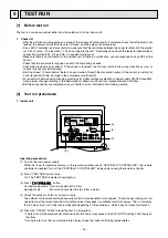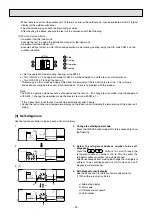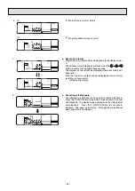
• In the case of the test run, the OFF timer will activate, and the test run will automatically stop after two hours.
• The room temperature display section shows the control temperature for the indoor units during the test run.
• Check that all the indoor units are running properly for simultaneous twin and triple operation.
Malfunctions may not be displayed even if the wiring is incorrect.
(*1)
After turning ON the power,the system will go into startup mode,and the remote controller operation lamp (red) and
the room temperature display section’s “H0 ” will flash. Also, in the case of the indoor substrata LEDs, LED 1 and
LED 2 light up (when address is 0) or become dim (when address is not 0), and LED 3 flashes. In the case of the
outdoor substrata LED display, –
and – are displayed alternatively at 1-second intervals.
• If one of the above operations does not function correctly, the following causes should be considered, and if
applicable, dealt with. (The following symptoms have been determined under test run mode. Note that “startup” in
the chart means the *1 display above.)
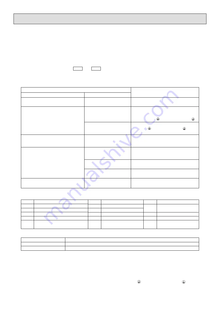
Remote controller is displaying “H0”, and operation is
not possible.
After power is turned ON,“H0 ” is displayed for 3 mins.,
then error code is displayed.
Power is turned ON,and “EE” or “EF” are displayed
after “H0” is displayed.
Display messages do not appear even when remote
controller operation switch is turned ON (operation
lamp does not light up).
Operation display appears but soon disappears even
when remote controller operations are executed.
After “startup” display,“00” is displayed
(correct operation).
After “startup” display,error code is
displayed.
After “startup” display, “F1” (negative
phase) is displayed.
After “startup” display, “00” or “EE” is
displayed (“EE” is displayed when a test
run is made).
After “startup” display, “EA” (error for
number of units) or “Eb” (unit number
error) is displayed.
After “startup” display, “00” is displayed
(correct operation).
After “startup” display, “00” is displayed
(correct operation).
After “startup” display, “00” is displayed
(correct operation).
• After power is turned ON, system startup lasts for about
2 mins., and “H0” is displayed (correct operation).
• Outdoor unit ’s safeguard installation connector is open.
• Negative phase and open phase of outdoor unit’s power
terminal board.
(Single phase: L, N, /triple phase: L1, L2, L3, N, )
• Incorrect connection of outdoor terminal board (Single
phase: L, N, /triple phase: L1, L2, L3, N, grounding
and S1, S2, S3)
• Outdoor unit and indoor unit construction differ.
• Wiring for the indoor and outdoor unit is not connected
correctly. (Polarity is wrong for S1, S2, S3)
• Remote controller transmission wire short.
• There is no outdoor unit for address 0 (address is
something other than 0).
• Remote controller transmission wire burnout.
• After cancellation of function selection, operation is not
possible for about 30 secs. (correct operation).
Symptoms
Remote Controller Display
Outdoor Substrate LED Display
Cause
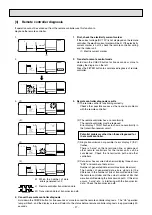
* Press the remote controller’s “CHECK” button twice consecutively to be able to run a self diagnosis. See the chart
below for content of error code displays.
LCD
Nonconformity content
P1
Suction sensor error
P2
Tubing (liquid) sensor error
P4
Drain sensor error
P5
Drain overflow safeguard operation
P6
Freezing/overheating safeguard operation
LCD
Nonconformity content
P8
Tube temperature error
P9
Tube (2-phase tube)sensor error
U0 ~ UP
Outdoor unit nonconformity
F1 ~ FA
Outdoor unit nonconformity
E0 ~ E5
Signal error between remote
controller and indoor unit
LCD
Nonconformity content
E6 ~ EF
Signal error between indoor and
outdoor units
----
No error history
FFFF
No relevant unit
See the chart below for details of the LED displays (LED 1, 2, 3) on the indoor substrate.
LED 1 (microcomputer power supply) Displays the ON/OFF of power for control.Check that this is lit during normal use.
LED 2 (remote controller feed)
Displays the ON/OFF of feed to wired remote controller. Is only lit for indoor unit linked to outdoor unit with address “00”.
LED 3 (indoor and outdoor signals)
Displays signal between indoor and outdoor units. Check that this is flashing during normal use.
2. Outdoor unit
(1) Check Items
• After installation of indoor and outdoor units,and piping and electric wiring work,check that the unit is free from leaks
of refrigerant,loosened connections,and incorrect polarity.
• Check that there is no negative phase and open phase. (The F1 message for negative phase and the F2 message
for open phase will flash at LED 1 on the outdoor substrate. If this happens,rewire correctly.)
• Measure the impedance between power terminals (Single phase: L, N, /triple phase: L1, L2, L3, N, ) and the
ground with a 500 V Megger and check that it is 1.0 M or more. Do not operate the equipment if measurement is
less than 1.0 M. *Never conduct this operation on the outdoor connection wiring terminals (S1, S2, S3) as this
causes damage.
- 24 -
Содержание PEH-RP10MYA
Страница 11: ... 2 Remote Controller Model PAR 20MAA 120 130 19 46 83 5 Front view Side view Rear view 9 ...
Страница 30: ... MEMO ...

