


OPTIONAL
PA
R
T
S
E-131
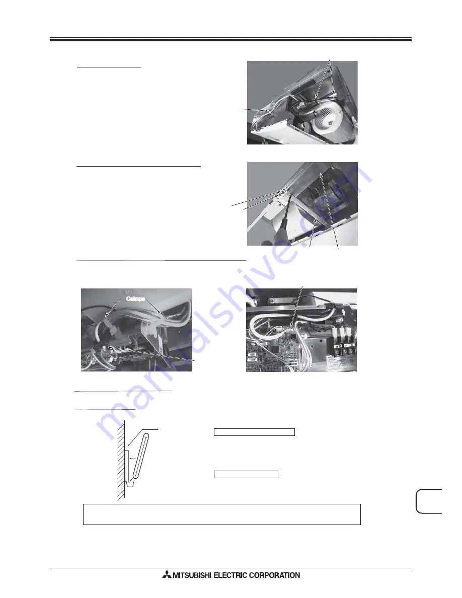
Connecting the receiver board connector to the control circuit board
Removing the beam and the electrical box cover
• Remove the beam.
• Loosen the two screws at the bottom of the electrical box cover,
and then slide the cover to the left to remove it.
• Pull down the electrical box.
{
Electrical box fixing screw
Electrical box cover fixing screw
Electrical box cover
Beam
• Pass the cord through the bush at the top right of the electrical box.
• Connect the connector to CN90 on the right of the control board.
• If the cord is loose, bundle it using the clamps under the above bush.
CN90
Bush
Calmps
Calmps
Remote control holder
• To install the wireless remote controller on a wall, first attach the remote control holder to a wall.
Fitting remote control into holder
Fix the remote control holder to the wall using
the 2 wood screws provided.
Insert the remote control into the holder.
Push the remote control against the wall.
Removing remote control
Ɣ
Pull the top of remote control forward.
NOTE : The remote signal will reach the receiver over a distance of approx. 7m in a straight line and approx. 45°
left or right. If the infrared receiver is affected by fluorescent light (especially, inverter type), it may not be
able to receive the signal. Take this into consideration when installing fluorescent lights or replacing them.
Also on the
opposite side
Reinstalling the removed components
• Reinstall the removed components in reverse order. (The brand lavel case is not needed.)
* The positions of the connectors may be different according to the model.
Please refer to the wiring diagram to confirm the positions of the connectors.
Laying out the lead wire
• Pass the lead wire for receiver through the retaining clips.
• Fix the lead wire for receiver with the clips on the ceiling side
of the unit.
Retaining clip
Clips on the ceiling side
Wireless Remote Controller Kit
for Ceiling Suspended models
PAR-SL94B-E