background image

27

8.  Initial setting

c) Name setting

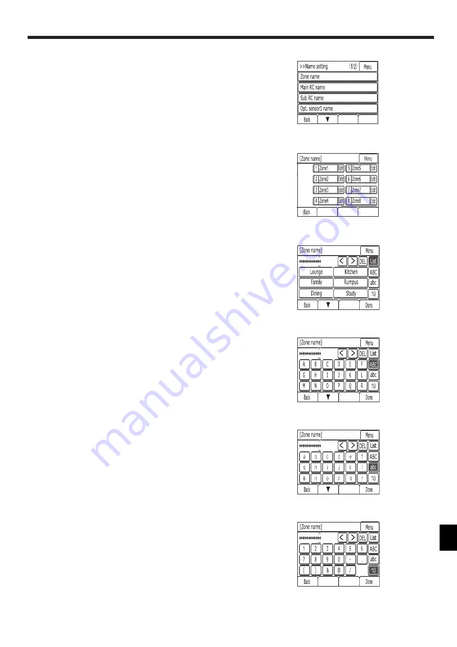
Set Zone name

Select [Zone name]

Touch [Edit] button of zone you want to change the name .

Display [List] screen.

• When you want to select the name from list,please touch the character string of 

the candidate.

[List] screen has 2 pages.Reshuffing of the page is done by touching [▼][▲].

• When you want to input the upper-case alphabet characters, please touch [ABC] 

button. The following screen is displayed.

The following screen has 2 pages. Reshuffing of the page is done by touching [▼]

[▲].

• When you want to input the lower-case alphabet characters, please touch [abc] 

button. The following screen is displayed.

The following screen has 2 pages. Reshuffing of the page is done by touching [▼]

[▲].

• When you want to input the number and sign, please touch [1()] button. The fol

-

lowing screen is displayed.

<Fig.  7.2.12>

<Fig.  7.2.13>

<Fig.  7.2.14>

<Fig.  7.2.15>

<Fig.  7.2.16>

<Fig.  7.2.17>

Содержание PAC-ZC80H-E

Страница 1: ...English ZONE CONTROLLER PAC ZC40L E PAC ZC80L E PAC ZC40H E PAC ZC80H E INSTALLATION MANUAL For safe and correct use read this manual thoroughly before installing the zone controller FOR INSTALLER ...

Страница 2: ...troller in an unusual environment If the zone control ler is installed or exposed to steam volatile oil including machine oil sulfu ric gas briny air the internal parts can be damaged Do not install the zone controller where combustible gases may leak be produced flow or accumulate If combustible gas accumulates around the zone controller it may cause fire or explosion When installing the zone con...

Страница 3: ...1 Check the parts Fig 2 1 1 The zone controller should be supplied with the following parts Parts Name Q ty 1 Zone control interface 1 2 Indoor unit zone controller cable 2m 1 3 Zone Remote controller 1 Fig 2 1 1 1 2 3 ...

Страница 4: ...mple where no common zone 4 damper motors 2 remote controllers and 2 optional temperature sensors are connected 3 1 System outline a With common zone b No common zone Spill zone setting required Symbol Legend Air flow Duct Damper Damper motor Air outlet Air inlet Temperature sensor Optional temperature sensor Spill zone Fig 3 1 Fig 3 2 Zone 1 2nd floor 1nd floor Zone 2 Zone 3 Zone 4 Ducted Indoor ...

Страница 5: ...DOOR UNIT Main RC Opt temp sensor 2 Optional Wi Fi INTERFACE Sub RC Power supply N 220 240V 50Hz Damper Motor Output a 24V damper motor model CN62 N L 3 2 1 TB3AC ZONE CONTROL INTERFACE TB3M TB24 CN61 CN64 CN63 CN66 CN65 CN68 CN67 SW1 ON 1 8 LED2 LED1 CN506 RED CN460 WHT CN201 RED CN202 RED Opt temp sensor 1 Opt temp sensor 2 CN105 RED INDOOR UNIT Optional Wi Fi INTERFACE Main RC Sub RC Damper Mot...

Страница 6: ...V AC damper motor connecting type PAC ZC40H E Maximum 8 of 240V AC damper motor connecting type PAC ZC80H E Zone remote controller Maximum 2 remote controllers can be connected 1 remote controller is included in the zone controller If you would like to use 1 more remote controller use the optional part Temperature sensor For the air conditioner control you can install 5 temperature sensors maximum...

Страница 7: ...the zone controller Fig 4 1 1 4 1 2 4 1 3 4 1 4 1 Remove 2 screws A Screw from zone controller and remove the cover See Fig 4 1 1 2 Install the 4 screws locally supplied in the 4 holes C Hole Note To prevent the unit from falling off the installation location select the appropriate screws locally supplied and secure the base horizontally to the appropriate installation location See Fig 4 1 2 A Scr...

Страница 8: ...not run the low voltage cables through a slot that the high voltage cables go through 2 Do not bundle power cables 240V together with other cables 3 Bundle cables as Fig 4 2 1 by using clamps 4 Remote controller cables sensor cables and other cables should be segregated by more than 50mm from each other until entry into the zone control inter face Also avoid cables running along metal surfaces Fig...

Страница 9: ...d an independent power source Connecting to the model with separate indoor outdoor unit power supplies Connecting to the model powered by outdoor unit Fig 4 2 3 Power supply wiring for 24V damper motor model Outdoor unit L Indoor unit TB24 TB3AC CN460 CN105 Zone control interface Transformer Accessory N S3 S2 S1 S3 S2 S1 N L Fig 4 2 4 Power supply wiring for 24V damper motor model TB24 TB3AC CN460...

Страница 10: ...rity Ensure that the damper motor and the damper motor cable to be used meet the following specification Locally supplied parts Specification Damper motor Voltage 24V AC Frequency 50Hz 60Hz Maximum Operation Current per damper 360mA or less Maximum Electric Power per damper 7VA or less Damper motor cable Wire diameter mm 0 48mm or more Maximum wiring length 30m or less Type RJ12 6 poler 6 core Tra...

Страница 11: ...bles to terminal bed please use electrical lugs Notes 1 Do not run the low voltage cables through a slot that the high voltage cables go through 2 Do not bundle power cables and damper cables together with other cables 3 Bundle cables as Fig 4 2 7 by using clamps 4 Remote controller cables sensor cables and other cables should be segregated by more than 50mm from each other until entry into the zo...

Страница 12: ...e control interface CN460 Indoor unit CN105 1 Zone control interface TB3AC L N Indoor unit 2 Min 1 0 Zone control interface unit earth 1 Min 1 0 Circuit rating Zone control interface TB3AC L N Indoor unit 220 240V AC Notes 1 Wiring size must comply with the applicable local and national codes 2 Remote controller Indoor unit connecting cords shall not be lighter than polychloroprene sheathed flexib...

Страница 13: ...lied parts Specification Damper motor Voltage 240V AC Frequency 50Hz 60Hz Maximum Operation Current per damper 70mA or less Maximum Electric Power per damper 12VA or less Damper motor cable Wire diameter mm 0 75 1 5mm Maximum wiring length 30m or less Type Type 60227 IEC52 or 53 When connecting damper motors ensure to connect them sequentially starting from zone 1 6 4 2 6 4 2 5 3 1 5 3 1 N L 3 SW1...

Страница 14: ...oom temperature Install the remote controller where no wires are routed around the temperature sensor on the controller or where no obstacles block the air inlet otherwise the sensor cannot measure accurate room temperature Do not install the controller where it is exposed to high concentration of acid alkaline or volatile organic compounds c Install the remote controller where occupancy and brigh...

Страница 15: ...ote Controller Required space around the remote controller To reduce the risk of electric shock malfunctions or fire seal the gap between the cables and cable access holes with putty Use caution when handling circuit boards to prevent damage from static elec tricity Although the circuit board is covered with an insulation sheet part of the cir cuit board is exposed Use extra caution not to let you...

Страница 16: ...nted to the top case Remove the front cover from the top case before installing the top case on the wall Refer to 1 Uninstalling the front cover on page 18 5 Zone Remote Controller Fig 5 1 6 Fig 5 1 5 3 Prepare the bottom case of the remote controller Take the following procedure only when performing direct wall installation and running the remote controller cable along the wall Cut out the thin w...

Страница 17: ...mps to prevent undue force from being applied to the terminal block and causing cable breakage Important 7 Set the M NET addresses To set the address turn the rotary switch with a precision slotted screwdriver 2 0mm 1 16 in W to a torque of less than 19 6 N to avoid the damage to the rotary switches Important Address range Address setting method Main remote controller 101 Not necessary since it is...

Страница 18: ...lat head screwdriver with a blade width of 4 5 5mm 5 32 7 32 in The use of a screwdriver with a narrower or wider blade tip may damage the controller casing To prevent damage to the controller casing do not force the driver to turn with its tip inserted in the slot To prevent damage to the control board do not insert the driver into the slot strongly Important 5 1 2 Connecting the zone remote cont...

Страница 19: ...o not insert remote controller cable and power source wiring in the same conduit Refer to Fig 4 2 1 and Fig 4 2 7 When wiring to TB3M use the ring type lugs and insulate them from the ca bles of adjoining terminals Fig 6 1 1 6 4 2 6 4 2 5 3 1 5 3 1 N L 3 SW1 ON 1 8 TB6A TB3AC LED2 LED1 ZONE CONTROL INTERFACE CN506 RED CN460 WHT TB3M 6 4 2 6 4 2 5 3 1 5 3 1 TB6B TB6C TB6D CN201 RED CN202 RED Main r...

Страница 20: ...ther with power cables The sensor part of the temperature sensor should be installed where user can not access It should be separated by supplementary insulation from areas the user can access 6 2 2 Installation 1 Select a place where the remote sensor will detect an average temperature of the room and where the sensor will not be subject to direct sunlight heat sources or in the airflow path from...

Страница 21: ...r remote controller and indoor unit zone controller cable using a band Regarding the initial setting of Wi Fi INTERFACE refer to the Wi Fi INTERFACE Installation Manual Fig 6 3 1 6 4 2 6 4 2 5 3 1 5 3 1 N L 3 SW1 ON 1 8 TB6 Wi Fi INTERFACE Option A TB3AC LED2 LED1 ZONE CONTROL INTERFACE CN506 RED CN460 WHT TB3M 6 4 2 6 4 2 5 3 1 5 3 1 TB6B TB6C TB6D CN201 RED CN202 RED Indoor Wifi ...

Страница 22: ...oor unit Please confirm the followings The cable is connected to CN460 of Zone control interface The cable is connected to CN105 of Indoor unit LED2 Or ange within 60s The communication between Remote controller and Zone control interface is normal Zone control interface cannot communicate with Remote controller Please confirm the followings The cable is connected to TB3M of Zone control interface...

Страница 23: ...or2 Common zone 1 Zone With or without Name Temp sensor Outlets 1 Spill zone 2 Zone1 Zone2 Zone3 Zone4 Zone5 Zone6 Zone7 Zone8 Common zone 1 Record the number of outlets and with without of common zone by referring to 3 1 System outline 2 Set when the system is without common zone When all zones are fully closed a zone which is set to as spill zone will open automatically ...

Страница 24: ...of Main RC After 5 min later Home screen will appear automatically b Sub remote conttoller The start up screen will appear of Sub RC If sub RC registered by Main RC HOME screen will appear automatically Fig 8 1 1 Fig 8 1 2 Fig 8 2 1 A password is required to access the Menu Service screen or some settings un der the Menu User screen The initial Service password is 9999 The initial User password is...

Страница 25: ...othing Optional Sensor2 Nothing Common Zone Nothing Zone1 Existence Zone2 8 Nothing Sensor of Zone1 8 Indoor Unit Outlet number of Zone1 1 Outlet number of Zone2 8 0 Spill setting of Zone1 Valid Spill setting of Zone2 8 Invalid c Name setting Set the name of Zone1 8 Main RC Sub RC Optional Sensor1 2 Refer to 1 Set menu c Name setting in page 27 Main RC Main RC Sub RC Sub RC Optional Sensor 1 Opt s...

Страница 26: ...layed When the error happens Request denied is displayed b Zone setting 1 Set the existence or not of Sub RC Optional Sensor 1 2 Common zone Yes Existence No not connected After that touch Next button 2 Set the existence or not of zone1 8 After that touch Next button 3 Select the zone you want to set in detail by touching button in Zone field 4 Select the sensor to assign to the zone sensor field ...

Страница 27: ...ut the upper case alphabet characters please touch ABC button The following screen is displayed The following screen has 2 pages Reshuffing of the page is done by touching When you want to input the lower case alphabet characters please touch abc button The following screen is displayed The following screen has 2 pages Reshuffing of the page is done by touching When you want to input the number an...

Страница 28: ...Cool Heat display e Telephone number f LED color adjustment R Red G Green B Blue Darken Lighten Reset Restores the de fault settings for the display color g Reset RC Fig 7 2 18 Fig 7 2 19 Fig 7 2 20 Fig 7 2 21 max 13 numbers ...

Страница 29: ...sta tus Except the set temperature normal operation functions are accessible during test run Mandatory 8 3 Function settings of zone control interface Mode Settings Mode No Setting No Initial setting Sensor determination method under multiple zones turned ON Average 1 1 1 Inlet temperature sensor 2 Fan control Normal 2 1 Invalid low fan speed 2 Invalid low and mid fan speeds 3 1 When the zones tur...

Страница 30: ...zone controller interface Investigate cause and replace blown fuse For 24V AC model ensure transformer is connected and supply correct voltage Check 24V AC transformer Ensure indoor unit is turned on and indoor fan is running Check operation of indoor unit and fan motor also check if unit is not in defrost mode or pre warming indoor heat exchanger in heating mode 3 No display on controllers Power ...

Страница 31: ...UF Compressor overcurrent interruption When compressor locked 1501 1102 1132 U2 Abnormal high discharging temperature 49C worked insufficient refrigerant 1302 U1 Abnormal high pressure 63H worked Overheating safeguard operation 1504 Ud 4230 U5 Abnormal temperature of heat sink 4400 U8 Outdoor unit fan safeguard stop 4250 U6 Compressor overcurrent interruption Abnormal of power module 1502 U7 Abnor...

Страница 32: ...his equipment generates uses and can radiate radio frequency energy and if not installed and used in accordance with the instructions may cause harmful interference to radio communications However there is no guarantee that interference will not occur in a particular installation If this equipment does cause harmful interference to radio or television reception which can be determined by turning t...

Страница 33: ...33 ...

Страница 34: ...34 ...

Страница 35: ...35 ...

Страница 36: ...IYODA KU TOKYO 100 8310 JAPAN Authorized representative in EU MITSUBISHI ELECTRIC EUROPE B V HARMAN HOUSE 1 GEORGE STREET UXBRIDGE MIDDLESEX UB8 1QQ U K Installers Please be sure to put your contact address telephone number on this manual before handing it to the customer ...

Отзывы: