background image

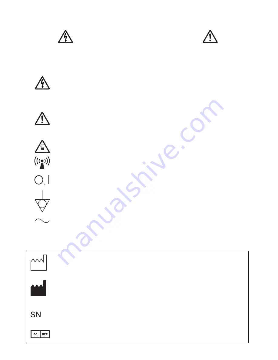
The lightning 

fl

 ash with arrowhead symbol, within an equilateral triangle, is 

intended to alert the user to the presence of uninsulated "dangerous voltage" 
within the product's enclosure that may be of suf

fi

 cient magnitude to constitute a 

risk of electric shock.

The exclamation point within an equilateral triangle is intended to alert the user 
to the presence of important operating and maintenance (servicing) instructions 
in the literature accompanying the appliance.

The “Caution, hot surface” symbol indicates that the marked item may be hot 
and should not be touched.

The “Nonionizing radiation” symbol

The “OFF/ON” symbol indicates connection to or disconnection from the mains, 
at least for mains switches.

The “Equipotentiality” symbol identi

fi

 es the terminals connected each other.  The 

potential of various parts of equipment or of a system is equalized.

The “Alternating current” symbol indicates that the equipment is suitable for 
alternating current only.

RISK OF ELECTRIC SHOCK DO NOT OPEN.

TO REDUCE THE RISK OF ELECTRIC SHOCK, DO NOT REMOVE COVER (OR 
BACK).
NO USER-SERVICEABLE PARTS INSIDE. REFER SERVICING TO QUALIFIED 
SERVICE PERSONNEL.

CAUTION: 

When you dispose of the unit or accessories, you must obey the law in the relative area 
or country and/or regulation in the relative hospital.

:  Manufactured on : to be combined with date code YYYY-MM

: Manufacturers 

Identi

fi

 cation (name address)

: Serial 

number

:  Authorised representative in the European Community

Содержание P-95DW

Страница 1: ...mplies with the requirements of the EC Directive 93 42 EEC DIGITALMONOCHROMEPRINTER MODEL P95DW P95DE OPERATION MANUAL THISOPERATIONMANUALISIMPORTANT TO YOU PLEASEREADITBEFOREUSINGYOUR DIGITALMONOCHROMEPRINTER DIGITALMONOCHROME PRINTER ...

Страница 2: ......
Страница 3: ...ications not expressly approved by the party responsible for compliance could void the user s authority to operate the equipment NOTE This equipment has been tested and found to comply with the limits for a Class A digital device pursuant to Part 15 of the FCC Rules These limits are designed to provide reasonable protection against harm ful interference when the equipment is operated in a commerci...

Страница 4: ... to the degree of protection against harmful ingress of water Ordinary equipment Enclosed equipment without protection against ingress of water According to the degree of safety of application in the presence of a flammable anesthetic mixture with air or with oxygen or nitrous oxide Equipment not suitable for use in the presence of a flammable anesthetic mixture with air or with oxygen or nitrous ...

Страница 5: ...icates connection to or disconnection from the mains at least for mains switches The Equipotentiality symbol identifies the terminals connected each other The potential of various parts of equipment or of a system is equalized The Alternating current symbol indicates that the equipment is suitable for alternating current only RISK OF ELECTRIC SHOCK DO NOT OPEN TO REDUCE THE RISK OF ELECTRIC SHOCK ...

Страница 6: ...USB cable with appropriate plug should be 2 m long or shorter comply with USB 2 0 standard High speed requirements and USB IF USB Implementers Forum approved This product is to be employed with medical equipment just for reference purpose not for medical diagnostic purpose Your MITSUBISHI ELECTRIC product is designed and manufactured with high quality materials and components which can be recycled...

Страница 7: ...ference page in this operation manual This page the previous pages for safety and page 25 for accessories This page and the previous pages for safety Page 3 for thermal paper Page 25 for accessories WARNING The use of ACCESSORIES and cables other than those specified with the exception of ca bles sold by the manufacturer of the Model P95DW P95DE as replacement parts for internal components may res...

Страница 8: ...interruptions and voltage variations on power supply input lines IEC EN 61000 4 11 Power frequency 50 60 Hz magnetic field IEC EN 61000 4 8 IEC EN 60601 test level 6 kV contact 8 kV air 2 kV for power supply lines 1 kV for input output lines 1 kV line s to line s 2 kV line s to earth 5 UT 95 dip in UT for 0 5 cycle 40 UT 60 dip in UT for 5 cycles 70 UT 30 dip in UT for 25 cycles 5 UT 95 dip in UT ...

Страница 9: ... an electromagnetic site survey a should be less than the compliance level in each frequency range b Interference may occur in the vicinity of equipment marked with the following symbol Compliance level 3 Vrms 3 V m NOTE1 At 80 MHz and 800 MHz the higher frequency range applies NOTE2 These guidelines may not apply in all situations Electromagnetic propagation is affected by absorption and reflecti...

Страница 10: ...timated using the equation applicable to the frequency of the transmitter where P is the maximum output power rating of the transmitter in watts W according to the transmitter manufacturer NOTE1 At 80 MHz and 800 MHz the separation distance for higher frequency range applies NOTE2 These guidelines may not apply in all situations Electromagnetic propagation is affected by absorption and reflection ...

Страница 11: ... 8 Front Panel 7 Rear Panel 8 INSTALLATION OF PAPER 9 10 EXAMPLE OF CONNECTION 11 PRINTING 12 13 ADJUSTMENT OF PRINT PICTURE 14 16 SETTING FUNCTION MODE 17 18 ERROR DISPLAY 19 21 STATUS AND MODES 22 USE OF CLEANING PAPER 23 MAINTENANCE 24 SPECIFICATIONS 25 1 CONTENTS ...

Страница 12: ...can cause extensive damage If any object should be inserted into the unit unplug the power cord then contact the sales dealer DO NOT PLACE ANYTHING ON THE UNIT Heavy objects placed on the unit can cause damage or obstruct proper ventilation PROTECT THE POWER CORD Damage to the power cord may cause fire or shock haz ard When unplugging hold by the plug only and remove carefully Never put heavy obje...

Страница 13: ...G A LONG ABSENCE Turn off the MAIN power switch and unplug the power cord during a long absence THERMAL PAPER Thermal papers listed in the page of SPECIFICA TIONS are available When the remaining length of the paper is about 10 25cm a color belt appears at the paper end Prepare for replacement of the paper If the remaining paper length is less than 10 25cm printing becomes uneven due to the uneven...

Страница 14: ... for use Any service after expiration of the warranty period will be chargeable Consult your deal er for advice TECHNICAL DESCRIPTION The supplier will make available on request such circuit diagrams component part lists descriptions calibration instructions or other information which will assist the USER s ap propriately qualified technical personnel to repair those parts of the EQUIPMENT which a...

Страница 15: ...ted from the host computer is printed via USB interface This printer creates prints electronically mainly in image processing and printing processing not optically or chemi cally The digital monochrome printer P95DW P95DE is intended for use as a hard copy device for an image generated by a diagnostic imaging equipment This product is intended to be used together with medical equipment and to be u...

Страница 16: ...re to keep the unit horizontal Take the unit out of the box carefully Take the unit out of the box by the following procedures Make sure to check the contents Unwrap the unit Accessories Cleaning paper Operation manual Printer driver 1 CD ROM Thermal paper AC power cord USB cable ...

Страница 17: ...ress this button and then turn the adjustment control to adjust the contrast of the print images See page 14 SHARP sharpness button Press this button and then turn the adjustment control to adjust the sharpness of the print images See page 14 FUNC function button Press this button and then turn the adjustment control to select the function mode See page 17 FEED button Press this button to feed the...

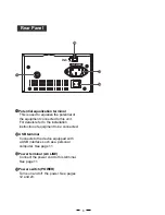
Страница 18: ...For details refer to the installation instruction of equipment to be connected USB terminal Connects to the device equipped with a USB interface such as a personal computer See page 11 Power terminal AC LINE Connect the power cord to this terminal See page 11 Power switch POWER Turns on and off the power See pages 12 and 23 ...

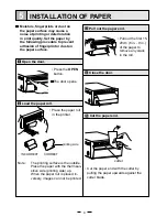
Страница 19: ...the paper with the thermsen sitive side printing side up When the paper roll is placed in versely images can not be printed Press the OPEN button The door opens printing side Place the paper roll in the printer Load the paper roll Open the door Pull out the first 15 20cm 6 in 9 in of the paper to remove any slack in the roll Pull out the paper end Close the door Cut the paper end Cut the paper end...

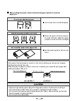
Страница 20: ...skewed from the print exit adjust the paper position so that it is fed out straight Do not allow slack in the paper roll Set the paper tightly to remove any slack If the side of the print paper is uneven or the core is sticking out the amount of paper feeding after printing may vary When the side of paper is uneven or the core is sticking out install the print paper after making the paper side eve...

Страница 21: ... in the CD ROM supplied with this unit How to open the ReadMe file Install the CD ROM in the CD ROM drive on your PC Double click on the CD ROM icon Double click on the ReadMe_E pdf Adobe Reader or Adobe Acrobat Reader is required to open ReadMe_E pdf file You can download Adobe Reader and Acrobat Reader free from the Web site of Adobe Systems Incorporated http www adobe com products acrobat Insta...

Страница 22: ...SHARP button during copy printing continuous printing is available Turn on the power Cut the printed paper Print a picture displayed on the screen Copy Printing Press the POWER switch on the rear panel to turn on the power Cut the printed paper with the cutter by tearing off the paper in the upper right direction Do not pull the paper in the horizontal direction The paper inside the unit may be di...

Страница 23: ...it has cooled down Avoid pulling out or holding the paper during printing or copying to prevent paper jam Do not touch the paper until printing or copying finishes To feed the paper press the FEED button on the front panel When you release the FEED button within about 1 second after starting paper feeding paper feeding automatically stops after feeding about 20 mm of the paper Paper Feeding ...

Страница 24: ...be printed Control panel For adjustment use the BRT CONT or SHARP button and the adjustment control Press the BRT CONT or SHARP button Press the BRT button to adjust the printer brightness The BRT indicator lights up Press the CONT button to adjust the contrast The CONT indicator lights up Press the SHARP button to adjust the sharpness The SHARP indicator lights up ...

Страница 25: ...lue will not be lost even when the power is turned off Turn the control clockwise to increase the value Store the set value Turn the control counterclockwise to decrease the value The setting value is displayed by the indicator example Setting range is 19 to 19 for brightness and contrast and 0 to 15 for sharpness ...

Страница 26: ...djust ment or setting mode When left without any operation of buttons and switches under the following conditions for more than 20 seconds this unit automatically returns to the standby status Indicator display In this case the newly set value is not memorized and the setting goes back to the value that was set before change While adjusting the printer brightness or printer contrast While adjustin...

Страница 27: ...ched as follows Stand by status Gamma curve setting Adjustment control lock setting USB iSerial number setting Functions Setting the function mode By turning the adjustment control you can change the setting value of each function mode By pressing the FUNC button again the setting value is memorized The set values will not be lost even when the power is turned off ...

Страница 28: ...rol functions The adjustment control is activated Default The adjustment control does not function When the ad justment control is turned an alarm sounds once Howev er when the adjustment control lock setting is selected in the FUNC button function the adjustment control function is activated You can select the setting of the USB iSerial number USB i Serial number 1 is disable Default USB i Serial...

Страница 29: ... If some images are waiting to be processed the following buttons function as described below COPY button Each time the COPY button is pressed the number displayed by the indicator increases as After the error is solved copy printing starts automatically FEED button When the number of copies has been set to more than one outstanding copies are cancelled When no image remains to be processed the bu...

Страница 30: ...he error is resolved the unit resumes printing from the interrupted image and finishes printing all the outstanding images Button input error Symptom An alarm tone is heard once in the following cases The indicator displays for one second and the button operation becomes invalid During adjusting the printer brightness or the printer contrast the adjustment control is turned exceeding the upper lim...

Страница 31: ...errupted image and finishes printing all the outstanding images Symptom When the thermal head does not automatically go down at the start of printing or paper feeding an alarm tone is heard When the thermal head does not automatically go up at the end of printing or paper feeding an alarm tone is heard The indicator displays and all the buttons become invalid If this error occurs while more than o...

Страница 32: ...During data receiving Fine adjustment of the picture brightness No paper Button input error Door is open Gear lock Fine adjustment of the picture contrast Remaining number of copies number of copies 1 to 99 100 to 199 200 Continuous copy printing Printer sharpness mode Fine adjustment of the picture sharpness Function mode Gamma curve setting Adjustment control lock setting USB iSerial number sett...

Страница 33: ... closed Close the door without taking out the cleaning paper Repeat the steps by 2 or 3 times and print 1 2 sheets to verify the cleaning effect Close the door Press the FEED button Take out the cleaning paper Turn on the power CAUTION It is recommended that after printing 10 rolls of paper the unit be cleaned using the supplied cleaning paper If the symptom of the dirty head is not corrected even...

Страница 34: ...ay appear on the print In this case eliminate the dust on to the rubber roller with a blower or a brush The regular cleaning using a lint free cloth etc which is moistened with ethyl alcohol is recommended Cleaning of Thermal Head When the thermal head is dirty with dust etc white spots or stripes may appear on the print In this case clean the thermal head according to 12 USE OF CLEANING PAPER Not...

Страница 35: ... dewing Atmospheric pressure 70 kPa 106 kPa External dimensions 6 1 x 3 4 x 9 4 154mm x 84 5mm x 240mm W x H x D Weight 6 2 lbs 2 8 kg Standard accessories Operation manual 1 copy AC power cord 1 piece USB cable 1 piece Thermal paper 1 roll Cleaning paper 1 sheet Printer driver 1 CD ROM Optional accessory Thermal paper K95HG KP65HM CE KP61S CE KP61B CE SERVICE INFORMATION Before requesting service...

Отзывы: