background image

En-15

● OPERATING INSTRUCTIONS ●

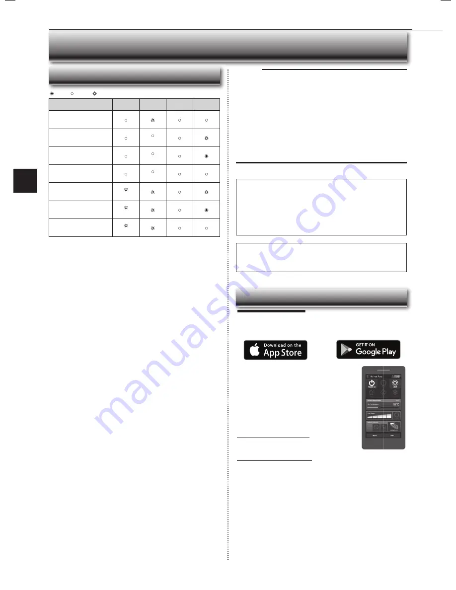
Description

ERR

(Orange)

NET

(Green)

MODE

(Orange)

UNIT

(Green)

Connection to server 

established, and connection to 

indoor unit failed
Connection to Router failed, 

and connection to indoor unit 

established

(*3)

Connection to Router failed, 

and starting up indoor unit 

connection 

(*3)

Connection to Router failed, 

and connection to indoor unit 

failed

(*3)

Connection to server failed, 

and connection to indoor unit 

established

(*2)

Connection to server failed, 

and starting up indoor unit 

connection 

(*2)

Connection to server failed, 

and connection to indoor unit 

failed

(*2)

(*2) Details of fl ash pattern 
•  Every  0.5  sec:  IP  address  setting  is  invalid.Check  DHCP  Settings  of  the 

Router, or check IP address settings of the Wi-Fi interface. If both settings are 

correct but still the problem persists, push RESET Button for more than 15 

seconds to retry the pairing.

•  Every  second:  DNS  setting  is  invalid.Check  DNS  Settings  of  the  Router, 

or check DNS address settings of the Wi-Fi interface. If both settings are 

correct but still the problem persists, push RESET


Button for more than 15 

seconds to retry the pairing.

•  Twice every 5 sec: Not connected to server. Check if the Router is connected 

to the internet.

•  Once  every  5  sec:  Not  communicating  with  server  properly.  Push  RESET 

Button for 2 seconds.

(*3) Details when NET LED is OFF
The Wi-Fi interface failed to connect to the Router. Check the following, and pair 

the Wi-Fi interface.
•  Make sure that the communication distance is not too far between the Wi-Fi 

interface and the Router.

•  Make sure 2.4GHz is enabled on dual band Routers.
•  Make sure that the Router uses WPA2-PSK(AES) encryption.
•  Make  sure  that  the  number  of  connected  devices  to  the  Router  does  not 

exceed the limit.

•  Make sure that WPS is working on the Router.
•  Make sure that the Router is compatible with the Wi-Fi interface.
•  If Static IP has been set - make sure it is correct as per Router network settings.

If a problem regarding connecting your Router and the Wi-Fi interface persists, 

please contact your local Mitsubishi Electric offi ce, as listed on the back of this 

guide. A list of compatible Routers is also available.

 : 

ON

 : 

Flashing

 : 

OFF

W

i-Fi INTERFACE SETTING UP (VGK TYPE ONLY)

Note:

•  Ensure that the Router supports the WPA2-AES encryption setting before 

starting the Wi-Fi interface setup.

•  The End user should read and accept the terms and conditions of the Wi-Fi 

service before using this Wi-Fi interface.

•  To complete connection of this Wi-Fi interface to the Wi-Fi service, the Rout-

er may be required.

•  This Wi-Fi interface will not commence transmission of any operational data 

from the system until the End user registers and accepts the terms and con-

ditions of the Wi-Fi service.

•  This Wi-Fi interface should not be installed and connected to any Mitsubishi 

Electric system which is to provide application critical cooling or heating.

•  Please write down the information regarding the Wi-Fi interface setting on the 

last page of this manual, when you set up this Wi-Fi interface.

•  At the time of relocation or disposal, reset the Wi-Fi interface to the factory 

default.

Mitsubishi Electric’s Wi-Fi interface is designed for communication to 

Mitsubishi Electric’s Wi-Fi service. Third party Wi-Fi interfaces cannot 

connect to Mitsubishi Electric’s Wi-Fi service. Mitsubishi Electric is not 

responsible for any (i) underperformance of a system or any product;  (ii) 

system or product fault; or (iii) loss or damage to any system or product; 

which is caused by or arises from connection to and/or use of any third 

party Wi-Fi interface or any third party Wi-Fi service with Mitsubishi Electric 

equipment.

For the latest information regarding Wi-Fi Control:
New Zealand based enquiries please visit: www.mitsubishi-electric.co.nz/wifi  
Australian based enquiries please visit: www.mitsubishielectric.com.au/wifi 

Once registered you will be able to control your heat 

pump with your smartphone, tablet or online account 

using an internet connection.

(For a list of compatible devices, please visit the 

Mitsubishi Electric website).

User Manual 

A copy of the user manual, terms & conditions and 

privacy policy can be downloaded at any time from the 

Mitsubishi Electric website.

Mitsubishi Electric New Zealand

www.mitsubishi-electric.co.nz/wifi 
Phone: 0800 639 434

Mitsubishi Electric Australia

www.mitsubishielectric.com.au/wifi 
Phone: 1300 728 119

Register Your Heat Pump(s)

Thank you for choosing a Mitsubishi Electric Heat Pump with Wi-Fi Control. 

Once your Wi-Fi interface is installed, either download the app (search term: 

Mitsubishi Wi-Fi Control) or visit our website to register your heat pump(s).

*Apple and the Apple logo are trademarks of Apple Inc., registered in the U.S. 

and other countries. App Store is a service mark of Apple Inc., registered in 

the U.S. and other countries.

*Google Play and the Google Play logo are trademarks of Google Inc.

Troubleshooting

Mitsubishi Electric Wi-Fi Heat Pump Control

JG79Y333H01_6th.indd   15

2018/06/19   10:28:21

Содержание MSZ-AP22VGD

Страница 1: ...STRUCTIONS For user To use this unit correctly and safely be sure to read these operating instructions before use MSZ AP22VGD MSZ AP25VGD MSZ AP35VGD MSZ AP42VGD MSZ AP50VGD MSZ AP22VGKD MSZ AP25VGKD MSZ AP35VGKD MSZ AP42VGKD MSZ AP50VGKD INDOOR UNIT ...

Страница 2: ...avoid a hazard When installing relocating or servicing the unit make sure that no substance other than the specified refrigerant R32 enters the refrigerant circuit Any presence of foreign substance such as air can cause abnormal pressure rise and may result in explosion or injury The use of any refrigerant other than that specified for the system will cause mechanical failure system malfunction or u...

Страница 3: ...use a portion of the core wire to break which may cause overheating or fire Do not charge or disassemble the batteries and do not throw them into a fire This may cause the batteries to leak or cause a fire or explosion Do not operate the unit for more than 4 hours at high humidity 80 RH or more and or with windows or outside door left open This may cause the water condensation in the air conditioner ...

Страница 4: ...lies with all Australia and New zealand regulrements for EMC and electrical safety CAUTION Improper handling may have consequences including injury or damage to building Do not step on unstable stepstool to set up or clean the Wi Fi interface It may cause injury if you fall down Do not use the Wi Fi interface nearby other wireless devices micro waves cordless phones or facsimiles It can cause malf...

Страница 5: ...SET button Page 5 Lid Slide the lid down to open the remote controller Slide it down further to get to the weekly timer buttons Only use the remote controller provided with the unit Do not use other remote controllers If 2 or more indoor units are installed in proximity to one another an indoor unit that is not intended to be operated may respond to the remote controller i save button Page 8 WEEKL...

Страница 6: ...ly 1 year However batteries with ex pired shelf lives last shorter Press RESET gently using a thin instrument If the RESET button is not pressed the remote controller may not operate correctly Note Press CLOCK gently using a thin instrument Note How to set remote controller exclusively for a particular indoor unit A maximum of 4 indoor units with wireless remote controllers can be used in a room T...

Страница 7: ...y fan and heating opera tions cannot be done at the same time When COOL DRY FAN is selected with one unit and HEAT with another or vice versa the unit selected last goes into standby mode Operation indicator lamp The operation indicator lamp shows the operation state of the unit Indication Operation state Room temperature The unit is operating to reach the set temperature About 2 C or more away fr...

Страница 8: ...For efficient air conditioning select the upper position for COOL DRY and the lower position for HEAT If the lower position is selected during COOL DRY the vane automatically moves to the upward position after 0 5 to 1 hour to prevent any condensation from dripping Swing The vane moves up and down intermittently Two short beeps are heard from the indoor unit when set to AUTO Always use the remote ...

Страница 9: ...ur preferred setting for COOL ECONO COOL HEAT mode and NIGHT MODE This enables you to select your preferred setting with a single push of the button A simplified set back function enables to recall the preferred preset setting with a single push of the button Press the button again and you can go back to the previous setting in an instance ECONO COOL OPERATION Press during COOL mode page 6 to start...

Страница 10: ...be seen in a bright room Noise level of the outdoor unit will not decrease during Multi system operation NIGHT MODE changes the brightness of the operation indicator disables the beep sound and limits the noise level of the outdoor unit 1 Press or during operation to set the timer ON timer The unit turns ON at the set time OFF timer The unit turns OFF at the set time or blinks Make sure that the c...

Страница 11: ...eekly timer OFF goes out Note The saved settings will not be cleared when the weekly timer is turned OFF Checking weekly timer setting 1 Press to enter the weekly timer setting mode blinks 2 Press or to view the setting of the particular day or number Press to exit the weekly timer setting Note When all days of the week are selected to view the settings and a different set ting is included among t...

Страница 12: ...mand response enabling devise DRED For further information consult your dealer Demand response represents the automated alteration of an electrical product s normal mode of operation in response to an initiating signal originating from or defined by a remote agent This unit supports 3 Demand Response Modes DRMs DRM Description of operation in this mode Operation indicator lamp Lit Not lit DRM 1 Com...

Страница 13: ...r washing with water dry it well in shade Front panel Air cleaning filter Anti Allergy Enzyme filter Every 3 months Remove dirt by a vacuum cleaner When dirt cannot be removed by vacuum cleaning Soak the filter and its frame in lukewarm water before rinsing it After washing dry it well in shade Install all tabs of the air filter Every year Replace it with a new air cleaning filter for best performance ...

Страница 14: ... Fi interface to the factory default No Item Description 1 MODE Button Selects modes 2 RESET Button Resets the system and ALL settings 3 ERR LED Orange Shows the network error state 4 NET LED Green Shows the network state 5 MODE LED Orange Shows the Access Point Mode state 6 UNIT LED Green Shows the indoor unit state 3 4 5 6 Information for users The following steps explain how to connect the Wi F...

Страница 15: ...on Description ERR Orange NET Green MODE Orange UNIT Green Communicating with server and communicating with indoor unit every 5 sec every 5 sec 1 Details of flash pattern Every 0 5 sec Searching for server Every second Registering the information of the Wi Fi interface to server ON Flashing OFF Once completed the MAC and ID will be filled in Add new unit Select Add and then control your heat pump vi...

Страница 16: ...of the Wi Fi service before using this Wi Fi interface To complete connection of this Wi Fi interface to the Wi Fi service the Rout er may be required This Wi Fi interface will not commence transmission of any operational data from the system until the End user registers and accepts the terms and con ditions of the Wi Fi service This Wi Fi interface should not be installed and connected to any Mit...

Страница 17: ... if the fan starts to rotate it stops soon When the outside temperature is low during cooling operation the fan operates intermittently to maintain sufficient cooling capacity Water leaks from the outdoor unit During COOL and DRY operations pipe or pipe connecting sections are cooled and this causes water to condense In the heating operation water condensed on the heat exchanger drips down In the h...

Страница 18: ...here inside the air conditioner resulting in water leakage or scattering of dew Electrical work Provide an exclusive circuit for the power supply of the air conditioner Be sure to observe the breaker capacity If you have any questions consult your dealer INSTALLATION PLACE AND ELECTRICAL WORK 1 Operate by COOL mode with the highest temperature set or FAN mode for 3 to 4 hours Page 6 This dries the...

Страница 19: ...ormation Indoor unit model name Indoor unit serial number Outdoor unit model name Outdoor unit serial number Wi Fi interface MAC address MAC Wi Fi interface serial number ID Wi Fi interface PIN PIN Wi Fi interface SSID SSID Wi Fi interface KEY KEY System commissioning date Wi Fi interface installation date Installer contact details Name Telephone number MEMO Indoor Outdoor Cooling Upper limit 32 C...

Страница 20: ...HEAD OFFICE TOKYO BUILDING 2 7 3 MARUNOUCHI CHIYODA KU TOKYO 100 8310 JAPAN JG79Y333H01 ...

Отзывы: