6 OPTIONS AND PERIPHERAL EQUIPMENT
6.2 Regenerative option
179
6
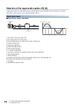
*1 Load torque converted into equivalent value on servo motor shaft TL can be calculated with the following formula.
T
L
= {(F
C
+ (
μ
× W
L
× g)) ×
Δ
S} / (2000 ×
π
×
η
)
*2 Load moment of inertia converted into equivalent value on servo motor shaft JL can be calculated with the following formula.
J
L
= J
L1
+ J
L2
+ J
L3
J
L1
is the load moment of inertia of the moving part, J
L2
is the load moment of inertia of the ball screw, and J
L3
is the load moment of
inertia of the coupling. J
L1
and J
L2
can be calculated with the following formulas.
J
L1
= W
L
× (
Δ
S / (20 ×
π
))
2
J
L2
= {(
π
× 0.0078 × (L
B
/ 10)) / 32} × (D
B
/ 10)
4
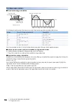
From the calculation results in (1) to (8), find the absolute value (Es) of the sum total of negative energies.
■
Losses of servo motor and servo amplifier in regenerative mode
The following table lists the efficiencies and other data of the servo motor and servo amplifier in the regenerative mode.
Inverse efficiency (
η
m
): Efficiency including some efficiencies of the servo motor and servo amplifier when rated (regenerative)
torque is generated at rated speed. Efficiency varies with the servo motor speed and generated torque. Because the
characteristics of the electrolytic capacitor change with time, allow inverse efficiency of approximately 10 % higher than those
shown above.
Capacitor charging (Ec): Energy charged into the electrolytic capacitor in the servo amplifier
Multiply the sum total of regenerative energies by the inverse efficiency, and subtract the capacitor charging from that result to
calculate the energy consumed by the regenerative option.
ER [J] =
η
m
• E
s
- E
c
Select a regenerative option that meets the requirements of the system by calculating the power consumption of the
regenerative option based on a one-cycle operation period tf [s].
PR [W] = ER/tf
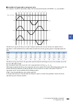
Regenerative
power
Torque T applied to servo motor [N•m]
Energy E [J]
(1)
(2)
T
2
= T
L
E
2
= 0.1047 • N • T
2
• t
1
(3)
(4), (8)
T
4
, T
8
= 0
E
4
, E
8
= 0 (No regeneration)
(5)
(6)
T
6
= T
L
E
6
= 0.1047 • N • T
6
• t
3
(7)
Servo amplifier
Inverse efficiency [%]
Capacitor charging [J]
MR-J5-10_
70
9
MR-J5-20_
85
9
MR-J5-40_
90
11
MR-J5-60_
90
11
MR-J5-70_
90
18
MR-J5-100_
90
18
MR-J5-200_
90
36
MR-J5-350_
90
40
MR-J5-500_
90
45
MR-J5-700_
90
70
MR-J5-60_4_
85
9
MR-J5-100_4_
85
12
MR-J5-200_4_
85
25
MR-J5-350_4_
85
35
(J
L
/
η
+ J
M
) • N
9.55 • 10
4
t
psa1
1
•
T
1
=
+ T
L
2
0.1047
E
1
=
• N • T
1
• t
psa1
-(J
L
•
η
+ J
M
) • N
9.55 • 10
4
t
psd1
1
•
T
3
=
+ T
L
2
0.1047
E
3
=
• N • T
3
• t
psd1
(J
L
/
η
+ J
M
) • N
9.55 • 10
4
t
psa2
1
•
T
5
=
+ T
L
2
0.1047
E
5
=
• N • T
5
• t
psa2
-(J
L
•
η
+ J
M
) • N
9.55 • 10
4
t
psd2
1
•
T
7
=
+ T
L
2
0.1047
E
7
=
• N • T
7
• t
psd2
Содержание MELSERVO-J5 MR-J5-G Series
Страница 1: ...MR J5 User s Manual Hardware MR J5 _G_ MR J5W_ _G_ MR J5 _A_ Mitsubishi Electric AC Servo System ...
Страница 2: ......
Страница 473: ...12 USING A FULLY CLOSED LOOP SYSTEM 12 7 Absolute position detection system 471 12 MEMO ...
Страница 477: ......

