background image

1-13 

English-12

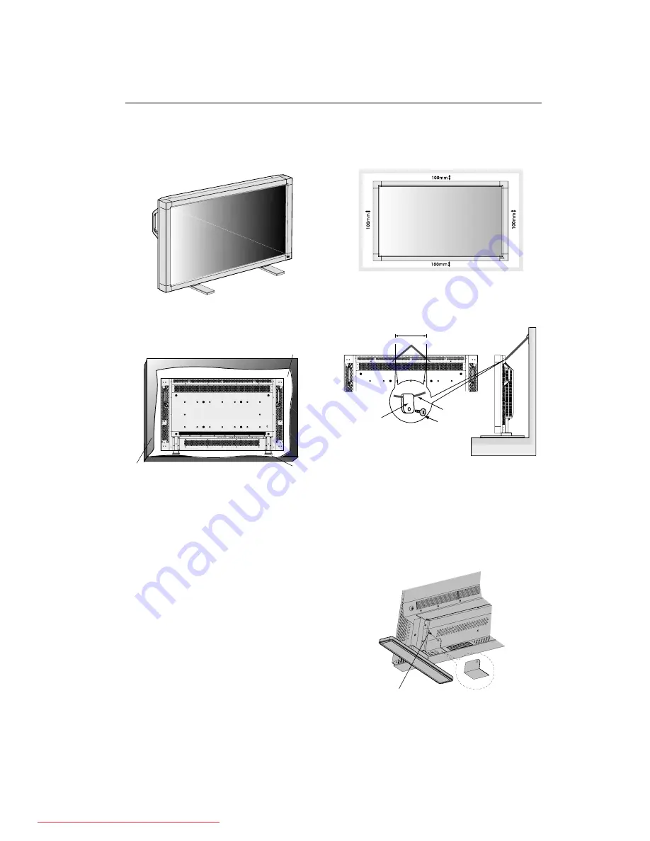
4. To avoid falling down

Fasten the LCD monitor to wall using a cord or chain, which
is sufficient to support the weight of the LCD monitor
(approx. MDT402S: 29.0kg / MDT461S: 32.8kg).

Before moving the LCD monitor, the cord or chain should be
removed.

5. To prevent the main power switch from

being changed

To prevent the ability to use the main power switch, please
attach the main switch, which is enclosed as an accessory.

NOTE:

With the main power switch cover in place, the main
power switch cannot be turned off. Remove main
power switch cover in order to switch off the display.

Clamper

Cord or Chain

250mm

Screw

You can attach mounting accessories to the LCD monitor in
one of the following two ways:

1. In the upright position

How to Mount and Attach Options to the LCD Monitor

2. Lay the screen face down

Lay the protective sheet on a table, which was wrapped
around the monitor when it was packaged, beneath the
screen surface so as not to scratch the screen face.

This device cannot be used or installed without the Tabletop
Stand or other mounting accessory. Failure to follow correct
mounting procedures could result in damage to the
equipment or injury to the user or installer. Product warranty
does not cover damage caused by improper installation.
Failure to follow these recommendations could result in
voiding your warranty.

When using with other mounting accessory, it must be a
VESA-compatible mounting method and the screws must be
M6 of size and 10mm or longer of length under consideration
of the thickness of the mounting method. (Recommended
torque: 470 - 635N•cm). MITSUBISHI ELECTRIC recommends
using mounting interface that comply with TÜV-GS and/or
UL1678 standard in North America.

Protective Sheet

Tabletop Stand

Table

Screw Holes

3. Ventilation Requirements for enclosure

mounting

To allow heat to disperse, leave space between surrounding
objects as shown in the diagram below.

Main switch cover

Screw

Downloaded From TV-Manual.com Manuals

Содержание MDT4025

Страница 1: ...1 1 User s Manual USER S MANUAL MANUEL UTILISATEUR MANUAL DEL USUARIO Downloaded From TV Manual com Manuals ...

Страница 2: ... LCD Monitor to a DVD Player English 16 Connect the LCD Monitor to a Stereo Amplifier English 17 Basic Operation Power On and Off modes English 18 Power Indicator English 19 Using Power Management English 19 Selecting a Video Source English 19 Picture Size English 19 Picture Mode English 19 Information OSD English 19 OSD On Screen Display Controls English 20 PICTURE English 20 SCREEN English 21 AU...

Страница 3: ... 15 pin mini D SUB to 15 pin mini D SUB 3 Please attach the ferrite cores on the Audio Cable Please see page 13 of this manual 2 This equipment has been tested and found to comply with the limits for a Class B digital device pursuant to part 15 of the FCC Rules These limits are designed to provide reasonable protection against harmful interference in a residential installation This equipment gener...

Страница 4: ...collection recycling center In the European Union there are separate collection systems for used electrical and electronic product Please help us to conserve the environment we live in TO PREVENT FIRE OR SHOCK HAZARDS DO NOT EXPOSE THIS UNIT TO RAIN OR MOISTURE ALSO DO NOT USE THIS UNIT S POLARIZED PLUG WITH AN EXTENSION CORD RECEPTACLE OR OTHER OUTLETS UNLESS THE PRONGS CAN BE FULLY INSERTED REFR...

Страница 5: ...ndle with care Allow adequate ventilation around the monitor so that heat can properly dissipate Do not block ventilated openings or place the monitor near a radiator or other heat sources Do not put anything on top of the monitor The power cable connector is the primary means of detaching the system from the power supply The monitor should be installed close to a power outlet which is easily acce...

Страница 6: ... contain the following LCD monitor Power Cord 3m for North America Power Cord 3m for EU Video Signal Cable SC B113 4m User s Manual Wireless Remote Control and AA Batteries Clamper x 3 Screw M4 x 8 x 4 CD ROM Band x 2 Ferrite Core x 2 Stand for the Independence x 2 Thumbscrew for stand x 2 Main switch cover Speaker Plug x 1set Required for optional Loudspeakers Install the stands at the time of un...

Страница 7: ...ontrol key lock function press both of and and hold down simultaneously for more than 3 seconds To resume back to user mode press both of and and hold simultaneously for more than 3 seconds 1 POWER button Switches the power on off See also page 18 2 MUTE button Switches the audio mute ON OFF 3 INPUT button Acts as SET button within OSD menu Selects which signal connected to the display is shown To...

Страница 8: ...N 1 2 3 Input audio signal from external equipment such as a computer VCR or DVD player 8 AUDIO OUT Output the audio signal from the selected AUDIO IN source 9 VIDEO INPUT OUTPUT CONNECTOR VIDEO IN connector BNC and RCA Input a composite video signal BNC and RCA are not available at the same time Use only one input VIDEO OUT connector BNC Output the composite video signal from the VIDEO IN source ...

Страница 9: ... See page 23 INPUT button Selects the picture in picture input signal CHANGE button Replaces to the main picture and sub picture 10 STILL button ON OFF button To switch the still picture mode on off CAPTURE button Captures the new picture Note Still does not work when pixel clock is greater than 108MHz 11 DISPLAY button To switch the information OSD on off See page 19 12 AUTO SETUP button To enter...

Страница 10: ...ng Range for the Remote Control Caution Important the remote control system may not function when direct sunlight or strong illumination strikes the remote control sensor of the LCD monitor or when there is an object in the path Handling the remote control Do not subject to strong shock Do not allow water or other liquid to splash the remote control If the remote control gets wet wipe it dry immed...

Страница 11: ...n leaks or bursting Be careful especially about the following points Place AA size batteries matching the and signs on each battery to the and signs of the battery compartment Don t mix battery types Don t combine new batteries with used ones It causes shorter battery life or leakage of batteries Remove dead batteries immediately to prevent battery liquid from leaking into the battery compartment ...

Страница 12: ...persistence please adjust the following items based on the application being used SCREEN SAVER See page 24 SIDE BORDER COLOR See page 24 DATE TIME See page 28 SCHEDULE See page 28 11 When the monitor is installed in the portrait position Remove the stands feet Left edge should be the upper edge from front view 12 Installing and removing stand How to install stand 1 Please turn monitor off 2 Place ...

Страница 13: ...monitor when it was packaged beneath the screen surface so as not to scratch the screen face This device cannot be used or installed without the Tabletop Stand or other mounting accessory Failure to follow correct mounting procedures could result in damage to the equipment or injury to the user or installer Product warranty does not cover damage caused by improper installation Failure to follow th...

Страница 14: ...re Ferrite core Attach the two Ferrite Cores to the both ends of PC Audio Cable Ferrite core Ferrite core Band Band To AUDIO 1 of monitor To connector of PC Connections Before making connections First turn off the power of all the attached equipment and make connections Refer to the user manual included with each separate piece of equipment Wiring Diagram LCD monitor Personal computer Personal com...

Страница 15: ... mini D sub 15 pin To connect the RGB 3 connector BNC on the LCD monitor use a signal cable which is available separately mini D sub 15 pin to BNC x 5 Select RGB 3 from the INPUT button When connecting one or more LCD monitors use the RGB OUT connector BNC LCD monitor LCD monitor second monitor BNC x 5 BNC x 5 PC or IBM compatible BNC x 5 Mini D sub 15 pin Mini D sub 15 pin To analog RGB output To...

Страница 16: ...andard Connect the LCD Monitor to a Computer with a Digital Output The RGB 1 IN connector also accepts a DVI D cable Input TMDS signals conforming to DVI standards To maintain display quality use a cable with a quality prescribed by DVI standards The AUDIO IN 1 2 and 3 can be used for audio input For connection select AUDIO 1 2 or 3 from the AUDIO INPUT button Mode selection see DVI MODE of page 2...

Страница 17: ...nnect a DVD player with an RCA pin jack to the BNC connector cable not provided Some DVD player may have different connectors such as DVD HD connector Y Cb Pb and Cr Pr Select DVD HD input mode from the INPUT button The AUDIO IN 2 and 3 both RCA can be used for audio input For connection select AUDIO 2 or AUDIO 3 from the AUDIO INPUT button Mode selection see DVI MODE of page 25 Connecting a DVD P...

Страница 18: ...e to connect the AUDIO OUT connector RCA on the LCD monitor and the audio input on the amplifier Do not reverse the audio left and right jacks The AUDIO IN is used for audio input The AUDIO OUT jack outputs sound from the selected Audio input Connecting to a Stereo Amplifier LCD monitor VCR or Laser disk player To audio right output Amplifier External speaker External speaker RCA RCA To audio left...

Страница 19: ...turn on the Main Power Switch on the LCD monitor Main Power Switch Power Button 2 Using the remote control Note Before operating the remote control be sure to turn on the Main Power Switch on the LCD monitor 3 Pressing the Main Power Switch Note When the Main Power Switch is used to power off the LCD the remote control and the power button will not activate the on mode Be sure to turn the Main Pow...

Страница 20: ...ooting on page 33 RGB1 2 3 Information OSD Signal Type NORMAL ZOOM DYNAMIC FULL WIDE 4 3 Squeeze Letter box NORMAL SIZE Recommended Size NORMAL Display by the inputed signal aspect ratio by PC signal or display in 4 3 aspect ratio at DVD HD or VIDEO signal FULL Display in entire screen WIDE Expand 16 9 letter box signal to entire screen ZOOM DYNAMIC Expand 4 3 pictures to the entire screen with no...

Страница 21: ...menu Press UP or DOWN button to select sub menu Press SET button to decide Press UP or DOWN and PLUS or MINUS button to select function or control which you like Press SET button to decide Press MENU or EXIT button to exit Remote Control Press UP or DOWN button to select Press INPUT button to decide Press UP or DOWN and PLUS or MINUS button to select function or control which you like Press INPUT ...

Страница 22: ...e position within the display area of the LCD Press button to move screen to UP Press button to move screen to DOWN Press button to expand the width of the image on the screen to the right Press button to narrow the width of the image on the screen to the left To change the snow noise of the image Adjusts the horizontal size by increasing or decreasing the setting Press button to expand the width ...

Страница 23: ...ress button to narrow the height of the image on the screen Selects the screen zoom mode Zoom mode will be selected when you select the ZOOM by pushing the SIZE button on remote controller When you select the CUSTOM you will be able to adjust optional horizontal and vertical size When you select 16 9 the screen will stretch 4 3 to 16 9 and then you will be able to adjust optional horizontal and ve...

Страница 24: ... CONFIGURATION 1 CONFIGURATION 2 ADVANCED OPTION SEL SET NEXT RETURN MENU EXIT MENU EXIT CONFIGURATION 1 AUTO SETUP AUTO ADJUST AUTO BRIGHTNESS POWER SAVE LANGUAGE SCREEN SAVER SIDE BORDER COLOR SEL SET NEXT RETURN MENU EXIT MENU EXIT ADJ RETURN MENU EXIT MENU POWER SAVE RGB ON OFF VIDEO ON OFF SEL EXIT CONFIGURATION 1 AUTO SETUP AUTO ADJUST AUTO BRIGHTNESS POWER SAVE LANGUAGE SCREEN SAVER SIDE BO...

Страница 25: ...ORDER COLOR CONFIGURATION 1 POWER SAVE LANGUAGE SCREEN SAVER COLOR SYSTEM SIDE BORDER COLOR CONFIGURATION RESET FACTORY RESET SEL SET NEXT RETURN MENU EXIT MENU EXIT FACTORY RESET RETURN MENU EXIT MENU NO YES SEL EXIT CONFIGURATION 1 POWER SAVE LANGUAGE SCREEN SAVER COLOR SYSTEM SIDE BORDER COLOR CONFIGURATION RESET FACTORY RESET SEL SET NEXT RETURN MENU EXIT MENU EXIT CONFIGURATION RESET RETURN M...

Страница 26: ...n Press button to move up side of the screen Press button to move down side of the screen LONG CABLE MANUAL RED DELY GREEN DELAY BLUE DELAY RED SHARPNESS GREEN SHARPNESS BLUE SHARPNESS SOG PEAK VIDEO EQ SYNC TERMINATE SEL RETURN MENU EXIT MENU ADJ 0 2 0 0 0 0 0 0 HI LO EXIT RETURN MENU EXIT MENU OFF TIMER ON 1 HOUR OFF ADJ SEL EXIT CONFIGURATION 2 LONG CABLE ON OFF LONG CABLE MANUAL OSD TURN OFF I...

Страница 27: ... the resolution as 1280x768 1360x768 Determines the resolution as 1360x768 Selects a level of black expansion In case of go under the black cut off level please adjust the Black level in moderation on OSD menu Selects a display gamma 1 2 2 2 2 4 3 S gamma 4 Native NOTE sRGB picture mode is standard and cannot be changed INPUT RESOLUTION INPUT RGB2 3 only BLACK LEVEL EXPANSION INPUT VIDEO only GAMM...

Страница 28: ...al divide V MONITORS Select number of vertical divide POSITION Select a position to expand the screen Frame compensation Works in tandem with TI LI NG to compensate for the width of the tile bezels in order to accurately display the image ENABLE Select YES the monitor will expand the selected position PIP POP SIDE by SIDE and STILL and DYNAMIC ZOOM mode will be disabled when TILING is activated RE...

Страница 29: ...e previous image was displayed For example if an image was on the monitor for one hour and a residual image remains the monitor should be turned off for one hour to erase the image As with all personal display devices We recommend displaying moving images and using a moving screen saver at regular intervals whenever the screen is idle or turning off the monitor when not in use Please set SCREEN SA...

Страница 30: ...aiming at the PRIMARY monitor The MENU OSD will appear on the selected ID No s monitor NOTE If ID No select OSD is showing at the PRIMARY monitor press DISPLAY button to clear this OSD HINT If you lost control by a reason of wrong setting IR CONTROL keep pressing during 5 sec or more the DISPLAY button The monitor will reset IR CONTROL to NORMAL NOTE 3 HOW TO SETUP SCHEDULE Using the SCHEDULE func...

Страница 31: ...hen using the following control commands all of the daisy chained monitors can be controlled at the same time from one monitor Reply and status commands however will only pertain to the primary monitor not secondary monitors 1 Interface This LCD monitor uses RXD TXD and GND lines for RS 232C control 2 Control command diagram The command is structured by the address code function code data code and...

Страница 32: ...us to host computer ex When Host computer ask Power status of monitor the status of monitor is powered on Command from computer Command from Monitor Detail of command 30 30 76 50 0D 0 0 v P enter Ask about the power status of monitor 30 30 76 50 31 0D 0 0 v P 1 enter Monitor is powered on Structure of the Read command Function Data Receive Function Data Receive ON vP 1 76 50 31 OFF stand by vP 0 7...

Страница 33: ...ter automatically optimizing display performance Intelligent Power Manager System Provides innovative power saving methods that allow the monitor to shift to a lower power consumption level when on but not in use saving two thirds of your monitor energy costs reducing emissions and lowering the air conditioning costs of the workplace Multiple Frequency Technology Automatically adjusts monitor to t...

Страница 34: ...mode is changed the OSD Image Adjust settings may need to be re adjusted Check the monitor and your display card with respect to compatibility and recommended signal timings If your text is garbled change the video mode to non interlace and use 60Hz refresh rate Image of component signal is greenish Check to see if the DVD HD input connector is selected LED on monitor is not lit no green or red co...

Страница 35: ...8 at 50Hz 60Hz to 85Hz 1280 x 768 at 50Hz 60Hz to 85Hz 1360 x 768 at 50Hz 60Hz to 85Hz 1280 x 1024 at 60Hz to 85Hz 1600 x 1200 at 60Hz Maximum Resolution Recommended Resolution NTSC PAL SECAM 4 43NTSC PAL60 HDTV 480i 480p 720p 1080i Power Supply 2 3 0 95A 100 240VAC 50 60Hz Power Consumption Max 230W Power save Less than 5W Power button OFF Main power switch ON Operational Temperature 5 40 C Envir...

Страница 36: ... 768 at 50Hz 60Hz to 85Hz 1280 x 768 at 50Hz 60Hz to 85Hz 1360 x 768 at 50Hz 60Hz to 85Hz 1280 x 1024 at 60Hz to 85Hz 1600 x 1200 at 60Hz Maximum Resolution Recommended Resolution NTSC PAL SECAM 4 43NTSC PAL60 HDTV 480i 480p 720p 1080i Power Supply 2 6 1 1A 100 240VAC 50 60Hz Power Consumption Max 260W Power save Less than 5W Power button OFF Main power switch ON Operational Temperature 5 40 C Env...

Страница 37: ... No Name 1 NC 2 RXD 3 TXD 4 NC 5 GND 6 NC 7 RTS 8 CTS 9 NC Pin Assignment of DVI connector 1 TX2 9 TX1 17 TX0 2 TX2 10 TX1 18 TX0 3 Shield TX2 TX4 11 Shield TX1 TX3 19 Shield TX0 TX5 4 NC 12 NC 20 NC 5 NC 13 NC 21 NC 6 DDC Serial Clock 14 5V power 22 Shield TXC 7 DDC Serial Data 15 Ground 5V 23 TXC 8 NC 16 Hot plug detect 24 TXC 5 10 15 1 6 11 1 6 5 9 Mini D SUB 15P Mini D SUB 9P 1 17 24 16 8 9 1 ...

Отзывы: