


6 - 10
6 Specifications of Peripheral Devices
MITSUBISHI CNC
6-7 Relay
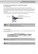
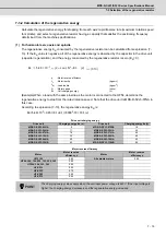
The input/output circuit to control the external signal such as external emergency stop input and relay
changeover signal output is wired.
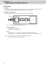
The input/output circuit for each unit is as follows.
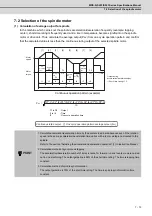
For a switch or relay to be wired, use a switch or relay that satisfies the input/output (voltage, current) conditions.
Input condition
Output condition
Switch ON
18VDC to 25.2VDC
5mA or more
Output voltage
24VDC ±5%
Tolerable output
current Io
40mA or less
Switch OFF
4VDC or less
1mA or less
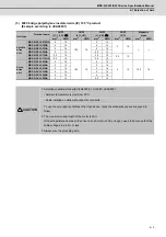
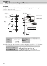
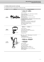
Interface name
Selection example
For digital input signal (CN9)
Use a minute signal switch which is stably contacted and operated even with
low voltage or current.
<Example> OMRON: G2A, G6B type, MY type, LY type
For digital output signal (CN9)
Use a compact relay operated with rating of 24VDC, 50mA or less.
<Example> OMROM: G6B type, MY type
CN9
DICOM
20
EMGX
5
19
12
2
DI1
DI2
2
DI
24G
3
9
15
13
D0COM
CN9
MBR
MC1
D02
24G
Input circuit
Output circuit
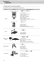
external
emergency stop
circuit
configuration
Example of an external
circuit configuration
RA for a motor brake
RA for starting an
external contactor
proximity
switch
24VDC
24VDC
Содержание MDS-D-SPJ3
Страница 1: ......
Страница 3: ......
Страница 5: ......
Страница 17: ......
Страница 19: ......
Страница 21: ......
Страница 27: ......
Страница 31: ......
Страница 39: ...1 8 ...
Страница 61: ...2 Specifications MITSUBISHI CNC 2 22 2 4 4 Unit outline dimension drawing 㧶㧟 㧶㧞 㧶㧝 㧶㧡 㧶㧢 㧶㧠D 㧶㧠C 㧔 㧕 Unit mm ...
Страница 65: ...2 26 ...
Страница 93: ...3 28 ...
Страница 169: ...5 58 ...
Страница 233: ...Appendix 2 10 ...
Страница 257: ...Appendix 4 20 ...
Страница 280: ......
Страница 284: ......


