6SHFL¿FDWLRQVDUHVXEMHFWWRFKDQJHZLWKRXWQRWLFH
© 2016 Mitsubishi Electric US, Inc.
24
HUMIDIFIER CONTROL
10
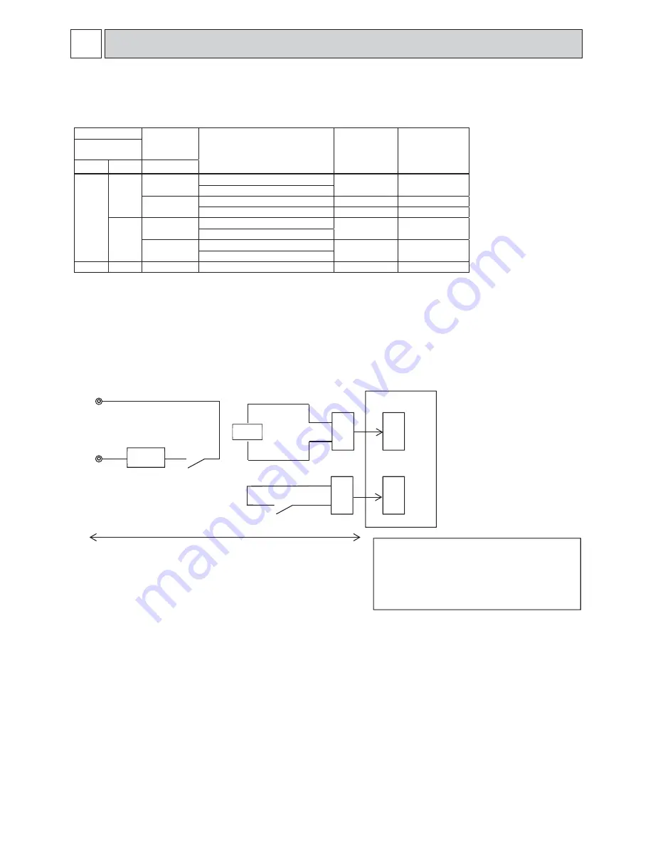
The below table shows how the field installed humidifier and fan speed is controlled.
Mode (function) No.
Wired remote controller
(RF thermostat)
Humidistat
output
Condition (no defrost/no error)
CN25 output
Fan speed
13 (113) 16 (116) CNF input
2
1
OFF
Heat operation & Thermo OFF
OFF
RC setting
Heat operation & Thermo ON
ON
Heat operation & Thermo OFF
OFF
RC setting
Heat operation & Thermo ON
ON
High
2
OFF
Heat operation & Thermo OFF
OFF
RC setting
Heat operation & Thermo ON
ON
Heat operation & Thermo OFF
ON
High
Heat operation & Thermo ON
-
-
Except for heat operation
OFF
RC setting
RC:Remote controller
The fan continues to run for 30 seconds after the humidifier stops.
A basic connection method is shown below.
CNF
CN25
Humidistat
XA
SVA
Humidifier
XA
Indoor unit
control board
On-site preparation
Maximum cable length is 10m(32ft)
pow
e
r source
Use XA relay having following specifications
Rated voltage:12VDC
Power consumption:1W or less
Humidistat:Minimum applicable load 1mA at DC
Contact rating voltage:15VDC or more
Contact rating current:0.1A or more
Humidifier
10-2. Installation
10-1. Control Specifications


