background image

B

 Manual Presser bar lifter

1 .  Turn the presser bar lifter in the direction of 

the arrow. This raises the presser foot.
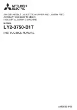
C

 Adjustment of the feed foot 

and the presser foot

1 .  Adjustment of alternating movement

( 1 )  The alternating movement on the feed foot 

and the presser foot can be adjusted by using 
the adjusting dial located on the top cover.

( 2 )  Face the desired number printed on the 

dial to the matching mark located on the 
top cover.

( 3 )  The number printed on the dial represents the 

possible protrusion of the feed foot and presser 
foot from the throat plate when the alternating 
movements on these are evenly set.

( 4 )  If the alternating movements are evenly 

set, they can be readjusted up to 2.0 to 
5.0 mm.

2 .  To change the balance of the alternating movements 

between the feed foot and presser foot

( 1 )  For example, to increase the rise of the feed 

foot, and decrease the rise of the presser foot.

①Remove the rubber plug located on the top 

cover.

②Turn the pulley until the presser foot is 

slightly raised from the throat plate.

③Loosen the set screw Ⓐ (on the right side) 

located on the feed lifting rock shaft crank 
(right).

④The built-in spring pulls down the presser 

foot until it makes contact with the throat 
plate. Then, tighten the set screw Ⓐ.

⑤This completes the adjustment, i.e., the 

protrusion of the presser foot has been 
decreased by a set distance. And, the 
vertical motion of the feed foot has been 
increased by that same distance.

( 2 )  As a contrary case (1), to decrease the rise 

of the feed foot, and increase the rise of the 
presser foot.

     First, turn the pulley until the feed foot is 

slightly raised from the throat plate. Next, 
loosen the screw Ⓐ. Finally, tighten the 
screw Ⓐ again. 

     This decreases the rise of the feed foot.

HOW TO USE

Presser bar lifter

Alternating movement 

adjusting dial

Matching mark

Presser foot

Feed foot

2.0 to 5.0 mm

Rubber plug

Set Screw Ⓐ

Feed lifting rock 

shaft crank (right)

— 8 —

Содержание LY2-3750-B1T

Страница 1: ...A180E301P02 INSTRUCTION MANUAL SINGLE NEEDLE LOCKSTITCH UPPER AND LOWER FEED AUTOMATIC UNDERTRIMMER INDUSTRIAL SEWING MACHINE LY2 3750 B1T MODEL ...

Страница 2: ...ion 1 If the machine s oil pan has an oil sump never operate the machine without filling oil in it 2 If the machine is lubricated by a drop oiler never operate the machine without lubricating 3 When a new sewing machine is operated verify the rotational direction of the pulley with the power on The pulley should rotate counterclockwise when viewed from the pulley 4 Verify voltage and single or thr...

Страница 3: ...g of the bobbin thread 4 3 Threading of the needle thread 5 4 Adjustment of feed stitch length and backstitch 5 5 Balance of threads tension 5 6 Adjustment of the needle thread tension 6 7 Adjustment of the bobbin thread tension 6 8 Adjustment of the presser foot pressure 6 9 Adjustment of the feed dog height 7 Adjustment of the feed dog inclination 7 A Adjustment of forward backward stitch length...

Страница 4: ...m adjust as follows 1 Disconnect the plug 12pins of cable from the machine head 2 Run the machine and stop at UP position 3 While holding the pulley insert the Adjusting tool in the hole Ⓐ then turn the tool 2 Adjustment of Down position When the pedal is Neutral the machine stops at Down position If marks deviate large than 3 mm adjust as follows 1 Disconnect the plug 12pins of cable from the mac...

Страница 5: ...ment of lubrication to the rotating hook Adjust the lubrication amount of the rotating hook by turning the screw Ⓐ Increase Decrease Screw Ⓐ 5 Adjustment of lubrication to the upper shaft Remove the face plate and adjust the lubrication amount by turning the upper shaft lubrication adjusting screw Increase Decrease Crank Upper shaft Maximum Standard Minimum Adjusting screw Ⓐ 6 Adjustment of the oi...

Страница 6: ...wer once then turning on again The same operation occurs for the detector malfunction or the line breakage 9 Installation of the belt cover 1 Install the belt cover on the machine side for safety Refer to the provided instruction document contained in the same package 2 Install the belt cover on the motor side for safety Precaution on operation 1 When the power is turned on or off keep foot away f...

Страница 7: ...ormally avoid fitting the needle with the groove facing backward Both needles DP 17 and DB 1 can be used Use the timing marks as shown in the figure 2 Winding of the bobbin thread Note When bobbin thread is wound keep the presser foot lifted Adjustment Tension of wound thread Slack winding is recommended for polyester thread and nylon thread Conically wound thread Move the thread guide toward smal...

Страница 8: ... the touch back switch Touch back switch In the case that the switch is turned to the arrow direction by 180 no backward stitching occurs even when the switch is pushed Use this function to avoid the malfunction such as unnecessary reverse stitching in the case that the fabric comes in contact with the switch during sewing 5 Balance of threads tension HOW TO USE Lead the thread rightward PUSH leve...

Страница 9: ...bin thread tension can be adjusted by turning the screw Ⓐ 8 Adjustment of the presser foot pressure 1 Adjust the presser foot pressure according to the fabric by turning the pressure adjusting screw 2 Pressure on the both the presser foot and the feed foot can be adjusted The adjusting screw position is factory adjusted as shown in the figure 3 Sewing pressure should be adjusted to the minimum req...

Страница 10: ... according to the material to be sewn as follows 1 Slightly loosen screw Ⓐ 2 While pressing the groove located in the eccentric pin by using a screwdriver turn the eccentric pin clockwise to lower the front end or counterclockwise to lift the front end 3 After adjusting tighten the screw Ⓐ Mark Eccentric pin Screwdriver Screw Ⓐ A Adjustment of forward backward stitch length 1 Loosen four set screw...

Страница 11: ...foot and decrease the rise of the presser foot Remove the rubber plug located on the top cover Turn the pulley until the presser foot is slightly raised from the throat plate Loosen the set screw Ⓐ on the right side located on the feed lifting rock shaft crank right The built in spring pulls down the presser foot until it makes contact with the throat plate Then tighten the set screw Ⓐ This comple...

Страница 12: ...ove adjust the feed regulator bracket This adjustment should insure a clearance of 12 mm between the periphery of pin Ⓑ located on the feed regulator bracket and the top cover mounting face located on the arm Tighten screws Ⓒ 4 Feed pitch adjustment of feed foot The ratio of the upper feed amount of the feed foot to the lower feed amount of the feed dog has been adjusted to 1 1 However the feed fo...

Страница 13: ... with a lower shaft cam So if you turn the machine by one revolution with the thread trimmer solenoid activated i e with the roller located on the cam follower crank 2 kept engaged with the thread trimmer cam the movable knife left will make contact with the needle breaking the contacting parts Activate the built in solenoid only when the normal thread trimming cycle is active lower position upper...

Страница 14: ... driving shaft 4 The stopper must be set to the flat on the knife driving shaft in such a way that the knife driving shaft is snug and smoothly turns in the shaft direction 5 Installing the thread trimmer solenoid unit 1 Operation stroke of the thread trimmer solenoid Standard operation stroke is 6 mm This stroke can be adjusted by using nut Ⓐ 2 Installing the unit The unit can be mounted by using...

Страница 15: ...amount of knives is 1 5 to 2 0 mm The engaging amount can be adjusted by properly mounting the driving crank 3 Adjustment of knives engaging pressure See the illustration In such a situation the movable knife left and the fixed knife should first make contact with each other This situation is standard If a thread is poorly cut particularly when it is thick slightly increase the engaging pressure T...

Страница 16: ...rimmers whose rotating hook has bobbin thread guide slit Ⓐ 2 Also use a bobbin case whose bottom has spring Ⓑ a capable of preventing racing 3 The bobbin provided in the package can be used G Adjustment of the gap between the pulley and the machine head The detector s reflection plate is installed on the inner side of the pulley So a correct distance must be kept with the detector body The gap bet...

Страница 17: ...6 0 Knee 16 0 Needle DP 17 22 DB 1 22 Hook vertical rotating hook Large Bobbin case With racing prevention spring Bobbin Made of steel for thread trimmer Lubrication system Automatic lubrication Thread trimmer Rotary trimming by left movable knife and right fixed knife Touch back Bed dimensions mm 517 178 Note The bobbin should be of high quality free from deformation Some materials and or sewing ...

Страница 18: ......

Страница 19: ......

Страница 20: ...Printed in Japan ...

Отзывы: