background image

C

 Adjustment of the thread take 

up spring

1 .   Adjusting movable range of the thread take 

up spring

( 1 )  To adjust the thread take up spring ① for 

the left thread, loosen the stopper stop screw 
② and move the stopper ③.


Note: In case of LU2-4710, adjust only step (1).

( 2 )  To adjust the thread take up spring ④ for 

the right thread, loosen the stopper stop 
screw ⑤ and move the stopper ⑥.

2 .   Adjusting intensity of the thread take up 

spring

( 1 )  Left thread:
 

Loosen the lock nut ⑦, and remove the face 
plate.


Loosen the screw ⑪ in the arm.


Turn the adjusting shaft ⑧.


After adjustment, tighten the screw ⑪ , and 
tighten the lock nut ⑦.


Note: In case of LU2-4710, adjust only step (1).

( 2 )  Right thread:
 

Loosen the screw ⑨, and turn the adjusting 
nut ⑩.


After adjustment, tighten the screw ⑨

D

 Adjustment of the outside presser 

foot and inside presser foot

1 .  Adjustment of alternating movement

( 1 )  The alternating movement on the outside 

presser foot and inside presser foot can be 
adjusted by using the adjusting dial located 
on the top cover.

( 2 )  Face the desired number printed on the dial 

to the matching mark located on the top 
cover.

( 3 )  The number printed on the dial represents 

the possible protrusion of the outside presser 
foot and inside presser foot from the throat 
plate when the alternating movements on 
these are evenly set.

( 4 )  If the alternating movements are evenly set, 

they can be readjusted up to 2.0 to 6.0 mm.

HOW TO USE

HOW TO USE

Decrease

Increase

⑨-Right side

⑧-Left side

⑦-Left side

⑩-Right side

Tighten

Loosen

Rubber plug

Matching mark

Alternating stroke 

adjusting dial

— 9 —

Содержание LU2-4710-B1T

Страница 1: ...A180E363P05 INSTRUCTION MANUAL LOCKSTITCH COMPOUND FEED AUTOMATIC UNDERTRIMMER INDUSTRIAL SEWING MACHINES LU2 4710 B1T Single Needle LU2 4730 B1T Double Needle MODEL ...

Страница 2: ...ion 1 If the machine s oil pan has an oil sump never operate the machine without filling oil in it 2 If the machine is lubricated by a drop oiler never operate the machine without lubricating 3 When a new sewing machine is operated verify the rotational direction of the pulley with the power on The pulley should rotate counterclockwise when viewed from the pulley 4 Verify voltage and single or thr...

Страница 3: ...D Adjustment of the outside presser foot and inside presser foot 9 E Instant alternating switch 11 F The stopper screw for adjusting the maximum alternating stroke 11 G Installing the feed regulator bracket 12 H Adjustment of the alternating stroke sensing potentiometer 12 I Timing between the rotating hook motion and the needle motion 13 J Adjustment of the feed dog height 14 K Relationship betwe...

Страница 4: ...ing the knee switch as the alternating switch connect 2 pin connector of OPTION B to the knee switch 3 Connect the urethane tube extended from the sewing machine head to A port of the solenoid valve Note For your safety always turn off the power switch whenever connect or disconnect connectors PREPARATION FOR OPERATION P port to the air supply source Air cylinder used for alternating movement is b...

Страница 5: ... head 2 Run the machine and stop at UP position 3 While holding the pulley insert the Adjusting tool in the hole Ⓐ then turn the tool 2 Adjustment of Down position When the pedal is Neutral the machine stops at Down position If marks deviate large than 5 mm adjust as follows 1 Disconnect the plug 12 pins of cable from the machine head 2 Run the machine and stop at Down position 3 While holding the...

Страница 6: ...nt of oil to the portions indicated by arrows in the below figure 1 Lubrication 1 Fill the oil reservoir with oil up to H mark Oil level should be periodically checked If oil level is found below L level replenish oil to H level For oil use MC70M specified by Mitsubishi Refer MC70M Specific gravity 15 0 86 g cm3 Viscosity 40 10 9 mm2 s USAGE PRECAUTION Oil level mark 3 ...

Страница 7: ...over load the power may not be turned off After the failure is eliminated the normal operation is resumed by turning off the power once then turning on again The same operation occurs for the detector malfunction or the line breakage 6 Installation of the belt cover 1 Install the belt cover on the machine side for safety Refer to the provided instruction document contained in the same package 2 In...

Страница 8: ...wound thread layer Amount of wound thread Loosen the winding amount adjustment screw to decrease thread winding amount and tighten the screw to increase thread winding amount HOW TO USE HOW TO USE Winding tension adjustment nut Even winding amount of 80 of full capacity Winding amount adjustment screw Thread guide Double Needle Insert the needle upto the bottom of needle clamp and tighten the scre...

Страница 9: ...ad or filament thread etc is used Pass the thread through thread guide B as well 2 With the thread take up lever located at the upper most position pass each needle thread in the order shown in the following figure Note Pushing the needle thread tension releasing button shown in the figure below opens the saucer of the needle thread tension adjuster and the needle thread can easily pulled out HOW ...

Страница 10: ...ng can be reversed by depressing the reverse sewing lever or pushing the touch back switch 6 Setting of bobbins 1 Pull out 5cm thread tail from bobbins 2 Put bobbins into hooks in the direction as the following figure 7 Adjustment of the needle thread guide Adjust the needle thread guide of the needle thread tension adjuster according to the fabric the thread and sewing condition Needle thread gui...

Страница 11: ... bobbin threads tension Balance of threads tension A Adjustment of needle threads tension Adjust needle threads tension by turning thread tension nuts B Adjustment of the presser foot pressure Adjust the presser foot pressure according to the fabric by turning the pressure adjusting screw HOW TO USE Pre tension nut Tighten Loosen Tighten Loosen Thread tension nut Weaken Strengthen A B C Balanced t...

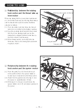
Страница 12: ... screw and turn the adjusting nut After adjustment tighten the screw D Adjustment of the outside presser foot and inside presser foot 1 Adjustment of alternating movement 1 The alternating movement on the outside presser foot and inside presser foot can be adjusted by using the adjusting dial located on the top cover 2 Face the desired number printed on the dial to the matching mark located on the...

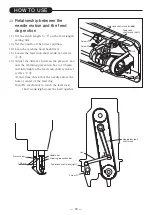
Страница 13: ... motion of the inside presser foot has been increased by that same distance 2 As a contrary case 1 to decrease the rise of the inside presser foot and increase the rise of the outside presser foot First turn the pulley until the inside presser foot is slightly raised from the throat plate Next loosen the screw Ⓐ Finally tighten the screw Ⓐ again This decreases the rise of the inside presser foot 3...

Страница 14: ... highest only while pressing the instant alternating switch F The stopper screw for adjusting the maximum alternating stroke The maximum alternating stroke can be adjusted with the stopper screw shown in the right figure The maximum alternating stroke is fixed at 6 mm when the sewing machine is shipped from the factory If the maximum alternating stroke is required to make smaller take the followin...

Страница 15: ...r switch 2 Remove all connectors except OPTION B connector 3 Remove the top cover in the condition which set the alternating stroke adjusting dial for scale 2 4 Turn on the power switch and then set the operation panel of the control box to the input display V2 at the programming mode E 5 Loosen the slotted bolt Ⓓ of the potentiometer crank At this time be careful not to give any bending torque to...

Страница 16: ...carf of the needle is 0 05 mm or lower 6 Tighten screws Ⓑ Ⓒ Note Be careful not to overtighten screws Ⓒ 7 Slide the large gear right and left so that the tip of the hook position is in the center of the needle and tighten screws Ⓓ Note Check the large gear and the hook saddle isn t in contact and its distance is less than 3 mm 8 Move the tip of the hook to the needle side by turning the pulley 9 I...

Страница 17: ...feed dog height is the position where the needle is at the top position Adjustment of the feed dog height 1 Lean the machine head backward 2 Turn the pulley by hand and stop it at the position where the feed dog rises to the maximum height 3 Loosen the feed bar screw 4 Vertically move the feed bar in the direction indicated by the arrow in the figure to adjust it to an adequate height 5 After adju...

Страница 18: ... black line on the boss of lower shaft bearing 3 If the timing mark is not in line with the black line remove the timing belt and install it again to adjust L Relationship between the rotating hook motion and the opener motion 1 Turn the pulley by your hand and stop it at the position where the opener holder is located most remotely from the throat plate 2 Check that the gap between the lug Ⓐ and ...

Страница 19: ...sure bar and the vibrating prevention bar to 10 5 mm and fully tighten the feed rock shaft crank set screws Ⓐ Ⓑ At this time check that the needle enters the hole at center of the feed dog Note Be careful not to touch the feed rock shaft crank right and the bed together HOW TO USE Link Needle bar Vibrating prevention bar Pressure bar Feed rock shaft crank right 10 5 mm Screw Ⓑ Needle bar rock shaf...

Страница 20: ...pposite side of bed with your left hand turn the pulley slowly with your right hand away from you as shown in the figure 2 The pulley will be stopped by the gear plate but turn the pulley more firmly 3 Release the pushbutton 4 The clutch device will be set as shown in the figure 3 Force applied to the safety clutch 1 The force applied to the safety clutch is the smallest when the white mark of the...

Страница 21: ...ertightened the link and the feed rock shaft crank right may not work P Adjustment of forward backward feed length The forward backward feed length can be adjusted by moving the eccentric pin as shown in the figure 1 Loosen the reverse stitch shaft crank screw 2 To increase forward stitch length turn the eccentric pin clockwise To increase backward stitch length turn the eccentric pin counterclock...

Страница 22: ...es 0 to 0 5 mm from the fixed knife as shown in the figure and tighten bolts Ⓐ and Ⓑ 2 Gap between the movable knife and the lug of inner hook 1 Turn the pulley and stop it at the position where the needle comes to the lowest 2 While pushing the cam follower crank turn the pulley and stop it at the position where the movable knife move to the position as shown in the figure 3 Turn the inner hook a...

Страница 23: ...oint S Adjustment of the thread trimmer cam 1 Turn the pulley and stop it at the position where the needle comes to the lowest 2 Put the cam roller into the thread trimmer cam groove by pushing the cam follower crank 3 Turning the pulley adjust the thread trimmer cam so that the movable knife starts moving when the green mark point on the pulley comes in line with the black mark point on the arm T...

Страница 24: ... clamp screws Ⓐ 4 The opening amount of the thread tension disc should be adjusted with the thread tension releasing roller Ⓑ mounted on the convex portion of the thread tension releasing cam as shown in the figure To adjust loosen screws Ⓒ and pull the wire 5 Make fine adjustments by loosening the nut Ⓓ 6 Loosen the nut Ⓓ and make the outer casing approach to the right to increase the opening amo...

Страница 25: ...n the thread trimmer mechanism and trimming failure adjust so that the thread can be trimmed with the minimum pressure 3 Move the movable knife and check that the thread can be sharply trimmed V Sharpening of the fixed knife If the fixed knife is dull it should be sharpened as shown in the figure Since it is very difficult to sharpen the movable knife replace it with a new one when it dulls HOW TO...

Страница 26: ...the Link clamp bolt Ⓙ 8 Turn the pulley and stop it at the position where the needle comes to the lowest 9 Loosen nuts Ⓖ and Ⓗ 10 Push the cam follower crank Ⓚ and adjust the pitman rod Ⓛ so that the cam roller can smoothly enter the thread trimmer cam groove 11 Adjustment of the cam groove and the cam roller a Put the cam roller into the thread trimmer cam groove by pushing the cam follower crank...

Страница 27: ...cm2 Thread trimmer Touch back Hook horizontal rotating hook Large Bobbin Made of aluminum for thread trimmer Lubrication system Automatic lubrication Bed dimensions mm 517 178 Needle gauge mm Standard 3 2 Special 6 4 12 7 19 25 4 The maximum sewing speed is fixed automatically according to the alternating up and down stroke However it is not fixed automatically to the stitch length So manually adj...

Страница 28: ...Printed in Japan ...

Отзывы: