


28. ENERGY MEASURING UNIT/ELECTRIC MULTI-MEASURING INSTRUMENT CONNECTION
28.4 GOT Side Settings
28 - 3
28
ENERG
Y MEAS
UR
ING
UNIT
/
ELECT
RIC M
UL
TI-
MEASURING
INSTRU
M
ENT
CO
NNECT
IO
N
29
GO
T
MUL
T
I-
DRO
P
CONNECTION
30
MUL
T
I-CHA
N
N
E
L
FUNCT
ION
31
F
A
TRANS
P
ARENT
FUNCTION
32
CO
NNE
C
TI
ON T
O
IA
I
ROBOT CON
T
ROLLER
33
CONNECTION
T
O
OMRON PLC
34
CO
N
N
EC
TI
O
N
T
O
OM
RON
T
E
MPERA
TURE
C
O
NT
ROL
LE
R
35
CONNECTION T
O
KEY
ENCE PLC
28.4 GOT Side Settings
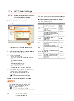
28.4.1 Setting communication
interface (Communication
settings)
Set the channel of the equipment connected to the GOT.
1.
Select [Common]
→
[Controller Setting] from the
menu.
2.
The Controller Setting window is displayed. Select the
channel to be used from the list menu.
3.
Set the following items.
• Manufacturer: MODBUS
• Controller Type: MODBUS
• I/F: Interface to be used
• Driver: MODBUS/RTU
4.
The detailed setting is displayed after Manufacturer,
Controller Type, I/F, and Driver are set.
Make the settings according to the usage
environment.
28.4.2 Communication detail settings
Click the [OK] button when settings are completed.
POINT
POINT
POINT
The settings of connecting equipment can be set and
confirmed in [I/F Communication Setting]. For details,
refer to the following.
17.1.2 I/F communication setting
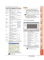
28.4.2 Communication detail settings
Make the settings according to the setting value of an
energy measuring unit/electric multi-measuring instrument
to be connected.
*1
Set either of the following values for the transmission speed.
[9600bps], [19200bps], [38400bps]
*2
Set [8bit].
*3
Set [HL Order].
*4
Make the settings to match the setting of the energy
measuring unit/electronic multi-measuring instrument.
POINT
POINT
POINT
(1) Communication interface setting by Utility
The communication interface setting can be
changed on the Utility's [Communication setting]
after writing [Communication Settings] of project
data.
For details on the Utility, refer to the following
manual.
12. COMMUNICATION INTERFACE
SETTING (COMMUNICATION SETTING)
(2) Precedence in communication settings
When settings are made by GT Designer3 or the
Utility, the latest setting is effective.
2.
3.
4.
Click!
Item
Description
Range
Transmission
Speed
*1
Set this item when change the
transmission speed used for
communication with the connected
equipment.
(Default: 19200bps)
9600bps,
19200bps,
38400bps,
57600bps,
115200bps
Data Bit
*2
Set this item when change the data length
used for communication with the
connected equipment. (Default: 8bit)
7bit/8bit
Stop Bit
*4
Specify the stop bit length for
communications. (Default: 1bit)
1bit/2bit
Parity
*4
Specify whether or not to perform a parity
check, and how it is performed during
communication. (Default: Even)
None
Even
Odd
Retry
Set the number of retries to be performed
when a communication error occurs.
(Default: 3times)
0 to 5times
Timeout Time
Set the time period for a communication
to time out. (Default: 3sec)
3 to 30sec
Host
Address
*4
Specify the host address in the connected
network. (Default: 1)
1 to 247
Delay Time
Set this item to adjust the transmission
timing of the communication request from
the GOT.
(Default: 0ms)
0 to 300ms
32bit Storage
*3
Select the steps to store two words (32-bit
data).
(Default: LH Order)
LH Order/
HL Order
Содержание GT16
Страница 1: ......
Страница 2: ......
Страница 46: ...1 4 1 OVERVIEW 1 1 Features ...
Страница 54: ...2 8 2 SYSTEM CONFIGURATION 2 2 System Equipment ...
Страница 60: ...3 6 3 SPECIFICATIONS 3 4 Battery specifications ...
Страница 72: ...5 8 5 UL cUL STANDARDS AND EMC DIRECTIVE 5 2 EMC Directive ...
Страница 102: ...6 30 6 OPTION 6 7 Connector Conversion Box ...
Страница 106: ...7 4 7 INSTALLATION 7 1 Installing Procedure ...
Страница 110: ...8 4 8 COMMUNICATION CABLE 8 1 Overview of Communication Cable ...
Страница 130: ...9 20 9 HANDLING OF POWER WIRING AND SWITCH 9 4 Switch Wiring ...
Страница 142: ...10 12 10 UTILITY FUNCTION 10 3 Utility Display ...
Страница 184: ...11 42 11 DISPLAY AND OPERATION SETTINGS GOT SET UP 11 4 Maintenance Function ...
Страница 202: ...12 18 12 COMMUNICATION INTERFACE SETTING COMMUNICATION SETTING 12 3 Ethernet Setting ...
Страница 226: ...13 24 13 DEBUG 13 3 Memory Data Control ...
Страница 248: ...14 22 14 SELF CHECK 14 2 Batch Self Check ...
Страница 350: ...15 102 15 DATA CONTROL 15 3 OS Project Information ...
Страница 410: ...19 22 19 TROUBLESHOOTING 19 2 Error Message and System Alarm ...
Страница 418: ...App 8 APPENDICES Appendix 3 Transportation Precautions ...
Страница 422: ...REVISIONS 4 ...
Страница 425: ......
Страница 426: ......
Страница 427: ......
Страница 428: ......
Страница 470: ......
Страница 510: ...21 22 21 COMPUTER LINK CONNECTION 21 6 Precautions ...
Страница 568: ...22 58 22 ETHERNET CONNECTION 22 5 Precautions ...
Страница 584: ......
Страница 626: ...25 14 25 SERVO AMPLIFIER CONNECTION 25 7 Precautions ...
Страница 632: ...26 6 26 ROBOT CONTROLLER CONNECTION 26 6 Precautions ...
Страница 647: ...MULTIPLE GOT CONNECTIONS 29 GOT MULTI DROP CONNECTION 29 1 ...
Страница 648: ......
Страница 659: ...MULTI CHANNEL FUNCTION 30 MULTI CHANNEL FUNCTION 30 1 ...
Страница 660: ......
Страница 675: ...FA TRANSPARENT FUNCTION 31 FA TRANSPARENT FUNCTION 31 1 ...
Страница 676: ......
Страница 742: ...31 66 31 FA TRANSPARENT FUNCTION 31 7 Precautions ...
Страница 744: ......
Страница 766: ...32 22 32 CONNECTION TO IAI ROBOT CONTROLLER 32 7 Precautions ...
Страница 802: ...34 10 34 CONNECTION TO OMRON TEMPERATURE CONTROLLER 34 7 Precautions ...
Страница 834: ...36 18 36 CONNECTION TO KOYO EI PLC 36 6 Device Range that Can Be Set ...
Страница 858: ...38 12 38 CONNECTION TO SHARP PLC 38 6 Device Range that Can Be Set ...
Страница 868: ...39 10 39 CONNECTION TO SHINKO TECHNOS INDICATING CONTROLLER 39 7 Precautions ...
Страница 902: ...42 6 42 CONNECTION TO TOSHIBA MACHINE PLC 42 6 Device Range that Can Be Set ...
Страница 908: ...43 6 43 CONNECTION TO PANASONIC SERVO AMPLIFIER 43 7 Precautions ...
Страница 970: ...48 12 48 CONNECTION TO FUJI TEMPERATURE CONTROLLER 48 7 Precautions ...
Страница 1052: ...52 26 52 CONNECTION TO AZBIL CONTROL EQUIPMENT 52 7 Precautions ...
Страница 1102: ...55 14 55 CONNECTION TO GE PLC 55 7 Precautions ...
Страница 1114: ...57 4 57 CONNECTION TO SICK SAFETY CONTROLLER 57 5 Device Range that Can Be Set ...
Страница 1128: ...59 2 59 CONNECTION TO HIRATA CORPORATION HNC CONTROLLER ...
Страница 1130: ...60 2 60 CONNECTION TO MURATEC CONTROLLER ...
Страница 1131: ...MICROCOMPUTER CONNECTION 61 MICROCOMPUTER CONNECTION SERIAL 61 1 62 MICROCOMPUTER CONNECTION ETHERNET 62 1 ...
Страница 1132: ......
Страница 1270: ...62 68 62 MICROCOMPUTER CONNECTION ETHERNET 62 8 Precautions ...
Страница 1271: ...MODBUS CONNECTIONS 63 MODBUS R RTU CONNECTION 63 1 64 MODBUS R TCP CONNECTION 64 1 ...
Страница 1272: ......
Страница 1292: ...64 12 64 MODBUS R TCP CONNECTION 64 7 Precautions ...
Страница 1293: ...CONNECTIONS TO PERIPHERAL EQUIPMENT 65 VNC R SERVER CONNECTION 65 1 ...
Страница 1294: ......
Страница 1298: ...65 4 65 VNC R SERVER CONNECTION 65 4 Setting in Personal Computer ...
Страница 1302: ...REVISIONS 4 ...
Страница 1305: ......
Страница 1306: ......