


13. DEBUG
13.1 Monitor Screens
13 - 1
9
HANDLING OF PO
WER WI
RI
N
G
AND SWIT
CH
10
UTIL
ITY FUNC
TION
11
DI
SPLA
Y
A
N
D
OP
ERA
T
IO
N
SE
TTI
N
GS
12
COMMUNICA
TION
INTE
RF
A
C
E
SE
TT
IN
G
13
DE
BUG
14
S
E
LF CHECK
15
D
A
TA
CONTROL
16
IN
ST
ALLA
TI
ON OF
COREOS,
B
O
OT
OS A
ND
ST
ANDA
RD MONI
TO
R OS
13. DEBUG
In this manual, the overview of the debuggingfunction and the operation procedure until displaying the screen are
described.
For display contents and operation procedure of debuggings, refer to the following manual.
GOT1000 Series Extended/Option Functions Manual for GT Works3
The following describes the functions available as the debugging function.
13.1 Monitor Screens
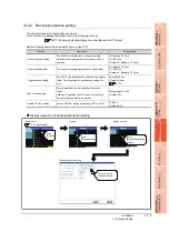
13.1.1 Function of monitor screens
The Monitor screens are designed to confirm the device status of PLC CPU and to make the response for PLC system
trouble more efficient.
The following shows the functions that can be performed with the Monitor screens.
Item
Description
Reference
Monitor screens
System monitor, Ladder monitor, Network monitor, intelligent module monitor, servo
amplifier monitor, Motion monitor, A list editor, FX list editor, SFC monitor, Ladder editor,
MELSEC-L troubleshooting, Log viewer, Motion SFC
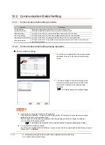
Debug setting
Q/L/QnA ladder monitor setting, Backup/restoration setting
Memory/data control
Backup/restoration function, GOT data package acquisition, CNC data I/O, Memory card
format, Memory information, USB device status display, SRAM control, Motion program
(SV43) I/O
Item
Description
System monitor
The device of PLC CPU and buffer memory of intelligent function module can be monitored or tested.
Ladder monitor
The program of PLC CPU can be monitored in ladder format.
Network monitor
The network status of the MELSECNET/H, MELSECNET(II), and CC-Link IE Controller Network can be
monitored.
Intelligent unit
monitor
Buffer memory in the intelligent function module can be monitored or the data can be changed on the
dedicated screen. And the signal status of I/O modules can be monitored.
Servo amplifier
monitor
Various monitor functions, parameter change, test operation, etc. of the servo amplifier are available.
Motion monitor
The servo monitoring and parameter settings of the motion controller CPU (Q series) are available.
CNC monitor
This function is not available for GT16 Handy.
A list editor
The sequence program of ACPU can be list edited.
FX list editor
The sequence program of FXCPU can be list edited.
SFC Monitor
The GOT can monitor and display SFC programs of the PLC CPU in the SFC diagram format (MELSAP3 or
MELSAP-L format).
Ladder editor
The sequence program of PLC CPU can be edited.
MELSEC-L
troubleshooting
The status of MELSEC-L CPU and buttons for functions related to the troubleshooting are displayed.
Log viewer
Logging data obtained through a high speed data logger module and LCUP can be browsed and the logging
data can be retrieved via GOT.
Motion SFC monitor Motion SFC program and device values in the Q series motion controller CPU can be monitored.
Motion program
(SV43) editor
This function is not available for GT16 Handy.
Содержание GT16
Страница 1: ......
Страница 2: ......
Страница 46: ...1 4 1 OVERVIEW 1 1 Features ...
Страница 54: ...2 8 2 SYSTEM CONFIGURATION 2 2 System Equipment ...
Страница 60: ...3 6 3 SPECIFICATIONS 3 4 Battery specifications ...
Страница 72: ...5 8 5 UL cUL STANDARDS AND EMC DIRECTIVE 5 2 EMC Directive ...
Страница 102: ...6 30 6 OPTION 6 7 Connector Conversion Box ...
Страница 106: ...7 4 7 INSTALLATION 7 1 Installing Procedure ...
Страница 110: ...8 4 8 COMMUNICATION CABLE 8 1 Overview of Communication Cable ...
Страница 130: ...9 20 9 HANDLING OF POWER WIRING AND SWITCH 9 4 Switch Wiring ...
Страница 142: ...10 12 10 UTILITY FUNCTION 10 3 Utility Display ...
Страница 184: ...11 42 11 DISPLAY AND OPERATION SETTINGS GOT SET UP 11 4 Maintenance Function ...
Страница 202: ...12 18 12 COMMUNICATION INTERFACE SETTING COMMUNICATION SETTING 12 3 Ethernet Setting ...
Страница 226: ...13 24 13 DEBUG 13 3 Memory Data Control ...
Страница 248: ...14 22 14 SELF CHECK 14 2 Batch Self Check ...
Страница 350: ...15 102 15 DATA CONTROL 15 3 OS Project Information ...
Страница 410: ...19 22 19 TROUBLESHOOTING 19 2 Error Message and System Alarm ...
Страница 418: ...App 8 APPENDICES Appendix 3 Transportation Precautions ...
Страница 422: ...REVISIONS 4 ...
Страница 425: ......
Страница 426: ......
Страница 427: ......
Страница 428: ......
Страница 470: ......
Страница 510: ...21 22 21 COMPUTER LINK CONNECTION 21 6 Precautions ...
Страница 568: ...22 58 22 ETHERNET CONNECTION 22 5 Precautions ...
Страница 584: ......
Страница 626: ...25 14 25 SERVO AMPLIFIER CONNECTION 25 7 Precautions ...
Страница 632: ...26 6 26 ROBOT CONTROLLER CONNECTION 26 6 Precautions ...
Страница 647: ...MULTIPLE GOT CONNECTIONS 29 GOT MULTI DROP CONNECTION 29 1 ...
Страница 648: ......
Страница 659: ...MULTI CHANNEL FUNCTION 30 MULTI CHANNEL FUNCTION 30 1 ...
Страница 660: ......
Страница 675: ...FA TRANSPARENT FUNCTION 31 FA TRANSPARENT FUNCTION 31 1 ...
Страница 676: ......
Страница 742: ...31 66 31 FA TRANSPARENT FUNCTION 31 7 Precautions ...
Страница 744: ......
Страница 766: ...32 22 32 CONNECTION TO IAI ROBOT CONTROLLER 32 7 Precautions ...
Страница 802: ...34 10 34 CONNECTION TO OMRON TEMPERATURE CONTROLLER 34 7 Precautions ...
Страница 834: ...36 18 36 CONNECTION TO KOYO EI PLC 36 6 Device Range that Can Be Set ...
Страница 858: ...38 12 38 CONNECTION TO SHARP PLC 38 6 Device Range that Can Be Set ...
Страница 868: ...39 10 39 CONNECTION TO SHINKO TECHNOS INDICATING CONTROLLER 39 7 Precautions ...
Страница 902: ...42 6 42 CONNECTION TO TOSHIBA MACHINE PLC 42 6 Device Range that Can Be Set ...
Страница 908: ...43 6 43 CONNECTION TO PANASONIC SERVO AMPLIFIER 43 7 Precautions ...
Страница 970: ...48 12 48 CONNECTION TO FUJI TEMPERATURE CONTROLLER 48 7 Precautions ...
Страница 1052: ...52 26 52 CONNECTION TO AZBIL CONTROL EQUIPMENT 52 7 Precautions ...
Страница 1102: ...55 14 55 CONNECTION TO GE PLC 55 7 Precautions ...
Страница 1114: ...57 4 57 CONNECTION TO SICK SAFETY CONTROLLER 57 5 Device Range that Can Be Set ...
Страница 1128: ...59 2 59 CONNECTION TO HIRATA CORPORATION HNC CONTROLLER ...
Страница 1130: ...60 2 60 CONNECTION TO MURATEC CONTROLLER ...
Страница 1131: ...MICROCOMPUTER CONNECTION 61 MICROCOMPUTER CONNECTION SERIAL 61 1 62 MICROCOMPUTER CONNECTION ETHERNET 62 1 ...
Страница 1132: ......
Страница 1270: ...62 68 62 MICROCOMPUTER CONNECTION ETHERNET 62 8 Precautions ...
Страница 1271: ...MODBUS CONNECTIONS 63 MODBUS R RTU CONNECTION 63 1 64 MODBUS R TCP CONNECTION 64 1 ...
Страница 1272: ......
Страница 1292: ...64 12 64 MODBUS R TCP CONNECTION 64 7 Precautions ...
Страница 1293: ...CONNECTIONS TO PERIPHERAL EQUIPMENT 65 VNC R SERVER CONNECTION 65 1 ...
Страница 1294: ......
Страница 1298: ...65 4 65 VNC R SERVER CONNECTION 65 4 Setting in Personal Computer ...
Страница 1302: ...REVISIONS 4 ...
Страница 1305: ......
Страница 1306: ......