background image

A-4

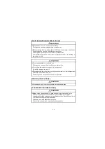
[STARTUP/MAINTENANCE PRECAUTIONS]

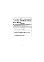
[DISPOSAL PRECAUTIONS]

[TRANSPORTATION PRECAUTIONS]

When power is on, do not touch the terminals.
Doing so can cause an electric shock or malfunction.

Before starting cleaning, always shut off GOT power externally in all phases. 
Not doing so can cause a unit failure or malfunction.
Undertightening can cause a short circuit or malfunction.
Overtightening can cause a short circuit or malfunction due to the damage of 
the screws or unit.

Do not disassemble or modify the unit.
Doing so can cause a failure, malfunction, injury or fire.

Do not drop the module or subject it to strong shock. 
A module damage may result.

Before touching the unit, always touch grounded metal, etc. to discharge static 
electricity from human body, etc.
Not doing so can cause the unit to fail or malfunction.

When disposing of the product, handle it as industrial waste.

Make sure to transport the GOT main unit and/or relevant unit(s) in the 
manner they will not be exposed to the impact exceeding the impact 
resistance described in the general specifications of the User's Manual for the 
GOT used, as they are precision devices.
Failure to do so may cause the unit to fail.
Check if the unit operates correctly after transportation.

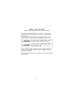
WARNING

CAUTION

CAUTION

CAUTION

Содержание GT15V-75R1

Страница 1: ...nal GOT MODEL GT15V 75V4R1 Video RGB Input Unit MODEL GT15V 75V4 Video Input Unit MODEL GT15V 75R1 RGB Input Unit Prior to use please read both this manual and detailed manual thoroughly to fully understand the product MODEL GT15V 75V4R1 U MODEL CODE 1D7M54 IB NA 0800348 G 1706 MEE ...

Страница 2: ...ns are ranked as WARNING and CAUTION Note that the caution level may lead to a serious accident according to the circumstances Always follow the instructions of both levels because they are important to personal safety Please save this manual to make it accessible when required and always forward it to the end user Indicates that incorrect handling may cause hazardous conditions resulting in death...

Страница 3: ...can cause the unit to fail or malfunction Use this unit in the environment that satisfies the general specifications described in the User s Manual for the GOT used Not doing so can cause an electric shock fire malfunction or product damage or deterioration Tighten the mounting screws within the specified torque range Undertightening can cause the GOT to drop short circuit or malfunction Overtight...

Страница 4: ...t doing so can cause a fire failure or malfunction Make sure to securely connect the cable to the connector of unit Incorrect connection may cause malfunctions Do not hold the cable by hand and pull it out from the unit When removing the cable from the unit make sure to hold the connector by hand and pull it Failure to do so may cause malfunctions or damage to the unit or cable Solder the coaxial ...

Страница 5: ...lure malfunction injury or fire Do not drop the module or subject it to strong shock A module damage may result Before touching the unit always touch grounded metal etc to discharge static electricity from human body etc Not doing so can cause the unit to fail or malfunction When disposing of the product handle it as industrial waste Make sure to transport the GOT main unit and or relevant unit s ...

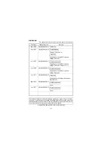
Страница 6: ...ompliance with the EMC and Low Voltage Directives Jun 2011 IB NA 0800348 E Compliance with the Radio Waves Act South Korea May 2015 IB NA 0800348 F Cover Jun 2017 IB NA 0800348 G Cover This manual confers no industrial property rights or any rights of any other kind nor does it confer any patent licenses Mitsubishi Electric Corporation cannot be held responsible for any problems involving industri...

Страница 7: ...splaying video images 7 2 4 2 Specifications of the cables 9 core combined cables used when displaying RGB screens 10 3 PART NAMES AND EXTERNAL DIMENSIONS 11 3 1 Part names and external dimensions of the video input unit 11 3 2 Part names and external dimensions of the RGB input unit 12 3 3 Part names and external dimensions of the video RGB input unit 13 3 4 External dimensions of the extension i...

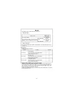
Страница 8: ...uantity GT15V 75V4 Video input unit 1 Mounting screw set 2 screws 2 stickers 2 Extend interface relay board 1 GT15V 75R1 RGB input unit 1 Mounting screw set 2 screws 2 stickers 2 Extend interface relay board 1 GT15V 75V4R1 Video RGB input unit 1 Mounting screw set 2 screws 2 stickers 2 Extend interface relay board 1 Manuals The following shows manuals relevant to this product For relevant manuals ...

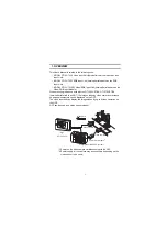
Страница 9: ... units with the GT1585V STBA GT1575V STBA hereinafter referred to as GOT the images taken by video cameras or screens on personal computers can be displayed on the GOT The video input unit can display the images taken by up to 4 video cameras on the GOT GOT can be used as a vision sensor monitor 1 Power on the video camera simultaneously with the GOT 2 Power supply for the camera may be necessary ...

Страница 10: ...ideo RGB input unit functions of both video input unit GT15V 75V4 and RGB input unit GT15V 75R1 are available When connecting to a personal computer GOT GT15V 75R1 1 When connecting to a video camera using an RGB output type vision sensor RGB output type vision sensor GOT GT15V 75R1 A 1254 348 B GOT 3 GT15V 75V4R1 Video camera 2 Computer PLCs for line control Do n ot mou nt not desmou nt a mo dule...

Страница 11: ...r screens cannot be displayed on the GOT at the same time To use the Video input unit RGB input unit and Video RGB input unit make the Communication Settings For setting details refer to GOT1000 Series Connection Manual For details of system configuration refer to GOT1000 Series Connection Manual For video input and RGB input functions refer to the GT Designer2 Version Screen Design Manual ...

Страница 12: ...em Color NTSC format PAL format interlaced format Monochrome EIA format CCIR format interlaced format Number of video input channels 4 channel Input signal IVp p 75 composite signal Display size dot s 640x480 possible to reduce to 320x240 160x120 720x480 possible to reduce to 360x240 180x120 1 Video external connection method Coaxial cable Applicable wire size 75 coaxial shield cable Maximum cable...

Страница 13: ...hod dot s Analog RGB SVGA 800x600 VGA 640x480 Number of video input channels 1 channel Input image signal 1Vp p 75 Synchronizing signal TTL 1k Display size dot s 800 600 refresh rate 60 72 75 Hz 640 480 refresh rate 60 72 75 85 Hz RGB external connection method D Sub15 pin Applicable wire size 9 core combined cable recommended Maximum cable length Refer to the specifications of the personal comput...

Страница 14: ...nnels 4 channel Input signal IVp p 75 composite signal Display size dot s 640x480 possible to reduce to 320x240 160x120 720x480 possible to reduce to 360x240 180x120 1 Video external connection method Coaxial cable Applicable wire size 75 coaxial shield cable RGB input section 3 RGB input method dot s Analog RGB SVGA 800x600 VGA 640x480 Number of video input channels 1 channel Input image signal 1...

Страница 15: ...for BNC connector and coaxial cable Item 3C 2V 5C 2V Construction Cable diameter 5 4mm 0 21in 7 4mm 0 29in Allowable bending radius 22mm 0 87in or more 30mm 1 18in or more Internal conductive material diameter 0 5mm 0 02in Annealed copper wire 0 8mm 0 03in Annealed copper wire Insulation material diameter 3 1mm 0 12in Polyethylene 4 9mm 0 19in Polyethylene External conductive material diameter 3 8...

Страница 16: ...uctive material in the specified dimensions as shown left Cut off the outer conductor in the same dimension as the taper part of the clamp and extend it over the clamp 4 Solder the contact to the tip of the internal conductive material 5 Insert the contact assembly of 4 into the plug shell and engage the plug shell with the nut Clamp Contact Gasket Washer Nut Plug shell Outer sheath Outer conducto...

Страница 17: ... longer video signals are attenuated and video images deteriorate When using a cable exceeding the length described in the following table it is recommended to correct video images using a video signal amplifier 4 Precautions for laying cable Consider wiring using double shielded coaxial cable in places that are subject to large amounts of noise The 5C 2V connector plug is applicable to double shi...

Страница 18: ... the personal computer and vision sensor 4 Precaution for cable creating The length of a cable differs depending on the personal computer and vision sensor to be used Male the create within the range of personal computer and vision sensor specifications Item Specifications Applicable cable Equivalent to SP23 23352A UL20276 SB Applicable wire size 9 core combined cable recommended 1 6 2 7 3 8 5 10 ...

Страница 19: ...ctor Connector mounted to the GOT 3 Extension connector Connector to which a back extension unit is installed 4 Connector for video RGB connection Connector connecting with the video RGB interface of GOT 5 Board fixing screw Screw for fixing the extend interface relay board 6 Mounting screw Mounting screws for fixing the unit to the GOT 7 Rating plate 3 6 1 2 6 GOT main unit 7 5 19 5 0 77 X 17 5 0...

Страница 20: ...onnector mounted to the GOT 3 Extension connector Connector to which a back extension unit is installed 4 Connector for video RGB connection Connector connecting with the video RGB interface of GOT 5 Board fixing screw Screw for fixing the extend interface relay board 6 Mounting screw Mounting screws for fixing the unit to the GOT 7 Rating plate GOT main unit X 133 5 24 2 5 0 10 113 5 4 47 105 4 1...

Страница 21: ...ce connector Connector mounted to the GOT 4 Extension connector Connector to which a back extension unit is installed 5 Connector for video RGB connection Connector connecting with the video RGB interface of GOT 6 Board fixing screw Screw for fixing the extend interface relay board 7 Mounting screw Mounting screws for fixing the unit to the GOT 8 Rating plate GOT main unit 4 7 1 3 7 8 6 2 19 5 0 7...

Страница 22: ...14 3 4 External dimensions of the extension interface relay board Unit mm inch 64 2 52 24 0 94 27 5 1 08 ...

Страница 23: ...of the GOT 3 Attach the extend interface relay board to the extend I F 2 side on the GOT After the installation detach the connector cover from the extend interface relay board 4 Fit the video RGB input unit in the GOT case 5 Fasten the video RGB input unit by tightening its mounting screws 4 places with tightening torgue 0 36 to 0 48 N m 4 3 Remove the connector cover ...

Страница 24: ... and the sticker When not installing an extension unit on the unit that has been installed in order to avoid receiving electrostatic stick accessory stickers to cover the top of mounting screws 4 places Keep the connector cover fixed Keep the sticker stuck as it is Point Remove the screws that fixes the extend interface relay board before removing the unit Above 6 5 6 Sticker Accessory sticker Acc...

Страница 25: ...17 MEMO ...

Страница 26: ... Direzionale Colleoni Palazzo Sirio Viale Colleoni 7 Agrate Brianza MB Italy Tel 39 039 60531 Mitsubishi Electric Europe B V Spanish Branch Carretera de Rubi 76 80 Apdo 420 08190 Sant Cugat del Valles Barcelona Spain Tel 34 935 65 3131 Mitsubishi Electric Europe B V French Branch 25 Boulevard des Bouvets 92741 Nanterre Cedex France Tel 33 1 55 68 55 68 Mitsubishi Electric Europe B V Czech Branch A...

Отзывы: