A.3
Error Code List
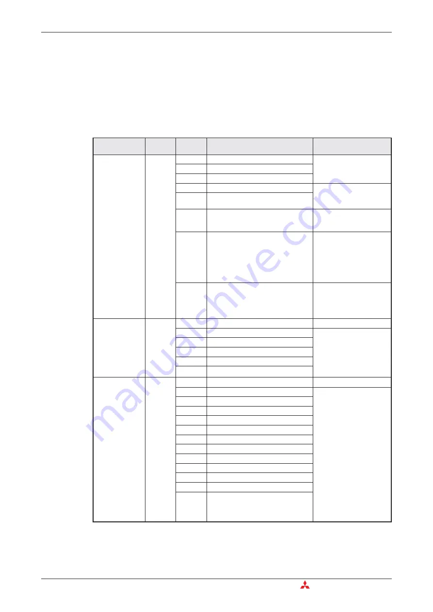
When an error has been detected in the PLC, the error code is stored in special registers D8060
to D8067 and D8438. The following actions should be followed for diagnostic errors.
Represented here are some of the most common error codes.
A.3.1
Error codes 6101 to 6409
Error Code List
Appendix
A - 10
MITSUBISHI ELECTRIC
Error
Special
Register
Error
Code
Description
Corrective Action
PLC
hardware error
D8061
0000
No error
—
6101
RAM error
6102
Operation circuit error
6103
I/O bus error (M8069 = ON)
Check for the correct con-
nection of extension cables.
6104
Powered extension unit 24 V failure
(M8069 = ON)
6105
Watchdog timer error
Check user program. The
scan time exceeds the value
stored in D8000.
6106
I/O table creation error (CPU error)
When turning the power ON to the
baseunit, a 24V power failure occurs in
a powered extension unit. (The error
occurs if the 24V power is not supplied
for 10 seconds or more after main
power turn ON.)
Check the power supply for
the powered extension
units.
6107
System configuration error
Check the number of the
connected special function
units/blocks. A few special
function units/blocks are lim-
ited the number to connect.
Communication
error between
PLC and program-
ming device
(FX
2N
and FX
2NC
only)
D8062
0000
No error
—
6201
Parity, overrun or framing error
Check the cable connection
between the programming
device and the PLC. This
error may occur when a
cable is disconnected and
reconnected during PLC
monitoring.
6202
Communication character error
6203
Communication data sum check error
6204
Data format error
6205
Command error
Serial
communication
error
D8063
0000
No error
—
6301
Parity, overrun or framing error
쎲
Inverter communication,
computer link and pro-
gramming: Ensure the
communication parame-
ters are correctly set ac-
cording to their applica-
tions.
쎲
N:N network, parallel
link, etc.: Check pro-
g r a m s a c c o r d i n g t o
applications.
쎲
Remote maintenance:
Ensure modem power is
ON and check the set-
t i n g s
o f
t h e
AT
commands.
쎲
Wiring: Check the com-
munication cables for
correct wiring.
6302
Communication character error
6303
Communication data sum check error
6304
Communication data format error
6305
Command error
6306
Communication time-out detected
6307
Modem initialization error
6308
N:N network parameter error
6312
Parallel link character error
6313
Parallel link sum error
6314
Parallel link format error
6320
Inverter communication error
Содержание FX2N-32CAN
Страница 1: ...MITSUBISHI ELECTRIC FACTORY AUTOMATION Programmable Logic Controllers GX IEC Developer ...
Страница 2: ......
Страница 4: ......
Страница 6: ......
Страница 10: ...IV MITSUBISHI ELECTRIC ...
Страница 18: ...Modular PLC Training Hardware Course Overview and Requirements 1 2 MITSUBISHI ELECTRIC ...
Страница 172: ...Monitoring Instances of Function Blocks Advanced Monitoring Functions 7 12 MITSUBISHI ELECTRIC ...
Страница 176: ...Device Edit 8 4 MITSUBISHI ELECTRIC ...
Страница 190: ...Assigning DUT Variables to Function Blocks Data Unit Types DUT 10 10 MITSUBISHI ELECTRIC ...
Страница 198: ...Array Example Single Dimension Array Arrays 11 8 MITSUBISHI ELECTRIC ...
Страница 219: ...Sequential Function Chart SFC SFC Elements Training Manual GX IEC Developer 14 3 ...
Страница 220: ...14 3 SFC configuration examples SFC configuration examples Sequential Function Chart SFC 14 4 MITSUBISHI ELECTRIC ...
Страница 230: ...Structured Text Program Example IEC Structured Text 16 4 MITSUBISHI ELECTRIC ...
Страница 248: ...Configuring GX IEC Developer to access the PLC on Ethernet Ethernet Communications 18 10 MITSUBISHI ELECTRIC ...
Страница 278: ...PLC Components Glossary Appendix A 18 MITSUBISHI ELECTRIC ...
Страница 283: ......


