
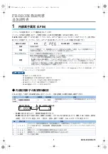


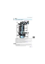


Main circuit terminals
9
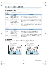
Cable gauge of main circuit terminals and earth (ground) terminals
Use an appropriate cable gauge to suppress the voltage drop to 2% or less.
If the wiring distance is long between the inverter and motor, the voltage drop in the main circuit will cause the motor torque to decrease especially at a low speed.
The following table indicates a selection example for the wiring length of 20 m.
• 200 V class (220 V input power supply, 150% overload current rating for 1 minute)
• 400 V class (440 V input power supply, 150% overload current rating for 1 minute)
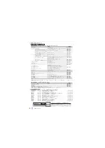
For 55K or lower, this cable gauge is with the continuous maximum permissible temperature of 75°C (HIV cable (600 V class 2 vinyl-insulated cable), etc.). Assumes
that the surrounding air temperature is 50°C or less and the wiring distance is 20 m or less.
For 75K or higher, this cable gauge is with the continuous maximum permissible temperature of 90°C or higher (LMFC (heat resistant flexible cross-linked polyethylene
insulated cable), etc.). Assumes that the surrounding air temperature is 50°C or less and the wiring is in-enclosure.
The terminal screw size indicates the size of the terminal screw for R/L1, S/L2, T/L3, U, V, W, PR, PX, P/+, N/-, P1, P3, and the screw for earthing (grounding).
The screw size for terminals PR and PX of the 200 V class 5.5K and 7.5K inverters is indicated in parentheses.
The screw size for earth (ground) terminal of the 200 V class 18.5 K or higher inverters is indicated in parentheses.
The screw size of terminal P/+ of the 110K inverter for connecting an option is indicated in parentheses.
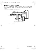
The line voltage drop can be calculated by the following formula:
Line voltage drop [V] =
×
wire resistance [m
Ω
/m]
×
wiring distance [m]
×
current [A] / 1000
Use a larger diameter cable when the wiring distance is long or when it is desired to decrease the voltage drop (torque reduction) in the low speed range.
NOTE
• Tighten the terminal screw to the specified torque. A screw that has been tightened too loosely can cause a short circuit or malfunction. A screw that has been
tightened too tightly can cause a short circuit or malfunction due to the unit breakage.
• Use crimp terminals with insulation sleeves to wire the power supply and motor.
Applicable inverter model
Terminal
Tightening
torque
N•m
Crimp terminal
Cable gauge
HIV cables, etc. (mm
2
)
FR-B
FR-B3
R/L1,
S/L2,
T/L3
U, V, W
R/L1,
S/L2,
T/L3
U, V, W
P/+,
P1
Earthing
(grounding)
cable
FR-B-750 to 2200
FR-B3-(N)400 to 2200
M4
1.5
2-4
2-4
2
2
2
2
FR-B-3700
FR-B3-(N)3700
M4
1.5
5.5-4
5.5-4
3.5
3.5
3.5
3.5
FR-B-5.5K
FR-B3-(N)5.5K
M5(M4)
2.5
5.5-5
5.5-5
5.5
5.5
5.5
5.5
FR-B-7.5K
FR-B3-(N)7.5K
M5(M4)
2.5
14-5
8-5
14
8
14
5.5
FR-B-11K
FR-B3-(N)11K
M5
2.5
14-5
14-5
14
14
14
8
FR-B-15K
FR-B3-(N)15K
M6
4.4
22-6
22-6
22
22
22
14
―
FR-B3-(N)18.5K
M8(M6)
7.8
38-8
38-8
38
38
38
14
FR-B-22K
FR-B3-(N)22K
M8(M6)
7.8
38-8
38-8
38
38
38
22
FR-B-30K
FR-B3-(N)30K
M8(M6)
7.8
60-8
60-8
60
60
60
22
FR-B-37K
FR-B3-(N)37K
M10(M8)
14.7
80-10
80-10
80
80
80
22
FR-B-45K
―
M10(M8)
14.7
100-10
100-10
100
100
100
38
FR-B-55K
―
M12(M8)
24.5
100-12
100-12
100
100
100
38
FR-B-75K
―
M12(M8)
24.5
150-12
150-12
125
125
125
38
Applicable inverter model
Terminal
Tightening
torque
N•m
Crimp terminal
Cable gauge
HIV cables, etc. (mm
2
)
FR-B
FR-B3
R/L1,
S/L2,
T/L3
U, V, W
R/L1,
S/L2,
T/L3
U, V, W
P/+,
P1
Earthing
(grounding)
cable
FR-B-750 to 3700
FR-B3-(N)H400 to 2200
M4
1.5
2-4
2-4
2
2
2
2
―
FR-B3-(N)H5.5
M4
1.5
2-4
2-4
2
2
3.5
3.5
FR-B-7.5
FR-B3-(N)H7.5K
M4
1.5
5.5-4
5.5-4
3.5
3.5
3.5
3.5
―
FR-B3-(N)H11K
M5
2.5
5.5-5
5.5-5
5.5
5.5
5.5
5.5
FR-B-15K
FR-B3-(N)H15K
M5
2.5
8-5
8-5
8
8
8
5.5
―
FR-B3-(N)H18.5K
M6
4.4
14-6
8-6
14
8
14
8
FR-B-22K
FR-B3-(N)H22K
M6
4.4
14-6
14-6
14
14
22
14
―
FR-B3-(N)H30K
M6
4.4
22-6
22-6
22
22
22
14
FR-B-37K
FR-B3-(N)H37K
M8
7.8
22-8
22-8
22
22
22
14
FR-B-55K
―
M8
7.8
60-8
60-8
60
60
60
22
FR-B-75K
―
M10
14.7
60-10
60-10
60
60
60
22
FR-B-90K
―
M10
14.7
60-10
60-10
60
60
80
22
FR-B-110K
―
M10(M12)
14.7
80-10
80-10
80
80
80
22


