518
SELECTION
3.5.3
Inverter-generated EMI and their reduction techniques
EMI generated by the inverter is largely classified into EMI
radiated by cables connected to the inverter and its main
circuit (input, output), magnetic and static induction EMI
affecting peripheral device signal lines routed near the
main circuit cable and electric path propagation EMI
transmitted over the power supply path line.
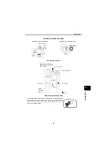
The EMI types and their paths are shown below.
Influence given to the peripheral devices by high-frequency
EMI of the inverter include the malfunctions of computers
instrumentation equipment, electronic equipment etc.
mainly caused by induction EMI and the malfunctions of
radios and nearby switches chiefly caused by radiated
EMI.
For details of noise reduction techniques, refer to the
Technical note No.21 (Noise and leakage currents).
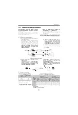
(1) EMI to electronic equipment
EMI to electronic devices include those transmitted
directly over the power supply line and ground cable
of the inverter (paths 7 and 8 in the figure above) and
those transmitted where the inverter power line and
electronic equipment signal line are coupled by
electromagnetic induction (paths 4 and 5 in the figure
above) or electrostatic induction (path 6 in the figure
above).
The power supply line of the electronic devices
should be different from the power line where the
inverter is connected, protected from EMI incoming
from the power supply line by a constant-voltage
power supply, insulating transformer, filters etc. and
separated from the wiring route. The I/O cables to
and from the electronic devices should be separated
from the inverter power cables. Basically, keep
inverter power cable as far away as possible from
cables which must not be subjected to EMI, or run
inverter power cable in separate iron shields
(ordinarily, iron ducts or metal pipes which should be
grounded) to minimize electromagnetic induction and
prevent a failure. The best way of grounding the
devices is independent equipment must not be
grounded jointly.
Especially as a countermeasure against EMI, run the
cables in the shortest distance and twist them. Also,
grounding should be carried out securely using a
large-diameter cable over the shortest distance.
EMI propagated through
power supply cable
Path 3)
Path 2)
Path 1)
EMI directly
radiated from inverter
Path 4), 5)
Air propagated
EMI
Path 6)
Electrical path
propagated EMI
Path 8)
Path 7)
Inverter
generated EMI
Electromagnetic
induction EMI
Electrostatic
induction EMI
EMI radiated from
power supply cable
EMI radiated from
motor connection cable
EMI from earth (ground)
cable due to leakage
current
Types of EMI generated
Instrument
Receiver
IM
Motor
Telephone
Sensor
1)
2)
3)
3)
8)
7)
5)
7)
4)
6)
Inverter
1)
Sensor
power supply
EMI paths
Содержание FR-A700 Series
Страница 245: ...279 2 PARAMETER PARAMETER MEMO ...
Страница 440: ...474 PARAMETER MEMO ...
Страница 522: ...556 SELECTION MEMO ...


