50CM-D180263-H02-C
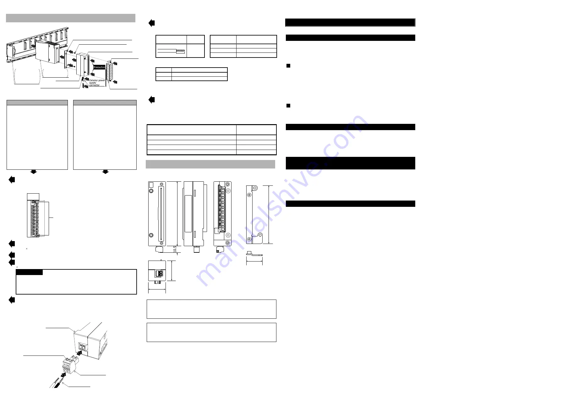
5.Part Names and Installation Method
Mounting Bracket (Conversion Adapter accessory)
Terminal block
installation screw (M3)
New Satellite JW Series
Terminal block
Conversion Adapter
Conversion Adapter installation screw
M3×25
1
2
3
5
7
2
2
4
4
6
External power supply connector
terminal screws (M2)
Mounting Bracket
M3.5×6 (Conversion Adapter accessory)
5
MELSEC-Q Series
or
MELSEC iQ-R Series
MELSEC-Q Series
or
MELSEC iQ-R Series
or
Q Series Large Type
(AnS Series size)
Base Unit
Module
5.1 Installation Method
Installation with the Control panel
Installation with the DIN rail
Install the Base unit (MELSEC-Q Series or
the AnS-size Q Series Large Type or the
MELSEC iQ-R Series) on the control
panel.
When replacing the current module with
the MELSEC-Q Series, It is recommended
to use the AnS-size Q Series Large Type
Base Unit because the Conversion
Adapter may interfere with the terminal
block of the neighboring module.
For how to install the Base Unit on the
control panel, refer to the “QCPU User's
Manual” or the “Q Series Large Type Base
Unit/Blank Cover (AnS Series Size) User's
Manual” or the “MELSEC iQ-R Module
Configuration Manual”.
Install the DIN rail mounting adapter
manufactured by Mitsubishi Electric to the
Base unit (MELSEC-Q Series or the AnS-
size Q Series Large Type or the MELSEC
iQ-R Series).
When replacing the current module with
the MELSEC-Q Series, It is recommended
to use the AnS-size Q Series Large Type
Base Unit because the Conversion Adapter
may interfere with the terminal block of the
neighboring module.
For how to install the Base Unit on the DIN
rail, refer to the “QCPU User's Manual” or
the “Q Series Large Type Base Unit/Blank
Cover (AnS Series Size) User's Manual” or
the “MELSEC iQ-R Module Configuration
Manual”.
①
Install the Module to the Base Unit. In addition, remove the terminal block attached
with the Module after loosening the terminal block installation screws (2 places up and
down).
Module
terminal block installation screw
(Secure it in two places, top and bottom.)
②
Secure the Mounting Bracket to the Module using the Mounting Bracket fixing screws
[M3.5 6 (Conversion Adapter accessory); two upper/lower locations].
③]
③
Mount the Conversion Adapter onto the Mounting Bracket.
④
Secure the Conversion Adapter using the Conversion Adapter installation screws (M3
25; 2 locations).
Precaution
Before tightening the installation screws, check that the Conversion Adapter has
been securely installed on the MELSEC-Q Series Module. Tightening the screws in
floating-off state or tilting state will damage the Conversion Adapter installation
screws and the Mounting Bracket.
⑤
Secure the terminal block of the New Satellite JW Series to the Conversion Adapter
with the terminal block installation screws (M3; two upper/lower locations).
【 Perform the following procedure only when replacing JW-212S/JW-212SA with
QY40P/QY50/QY70 or RY40NT5P】
Conversion Adapter
External power supply
connector (accessory)
Cables (DC/GND)
External power supply connector
terminal screws (M2)
⑦
⑥
⑥
Insert the connection cables to the terminals of the external power supply connector.
・Use connection cables in the applicable wire size.
Cables
Stripping
length
Item
Specifications
7㎜
7㎜
Applicable wire size
0.14 to 1.5mm
2
(24 to 16AWG)
Type
Stranded wire/single wire
Material
Copper
・Carry out wiring correctly after checking the terminal arrangement.
Terminal
Signal name
DC
External power supply 5/12/24VDC +
GND
External power supply 5/12/24VDC -
Then, tighten the external power supply connector terminal screws (M2) to secure the
connection cables.
⑦
Insert the external power supply connector to the Conversion Adapter securely.
6.2 Tightening Torque
Tighten the installation screws to the specified torque below. An inappropriate tightening
torque could cause the product to fall or result in a short circuit, product failure or malfunction.
Screw Location
Tightening Torque
Range
Mounting Bracket fixing screw (M3.5×6)
0.68 to 0.92N・m
Conversion Adapter installation screw (M3×25)
0.43 to 0.57N・m
Terminal block installation screw (M3)
0.5 to 0.6N・m
External power supply connector terminal screws (M2)
0.22 to 0.25N・m
6.External Dimensions
Unit: mm
1
02
27.4
31
.5
9
2
25.7
Conversion adapter
Mounting bracket
Duplication Prohibited
This manual may not be reproduced in any form, in part or in whole, without written
permission from Mitsubishi Electric Engineering Company Limited.
©2016(2018) MITSUBISHI ELECTRIC ENGINEERING COMPANY LIMITED ALL RIGHTS
RESERVED
MELSEC and MELSEC iQ-R is a registered trademark of Mitsubishi Electric Corporation in
Japan.
ERNT is a registered trademark of Mitsubishi Electric Engineering Company Limited in Japan.
All company and product names herein are either trademarks or registered trademarks of
their respective owners.
Product Warranty Details
Please confirm the following product warranty details prior to product use.
Gratis Warranty Terms and Gratis Warranty Range
If any fault or defect (hereinafter referred to as “Failure”) attributable to Mitsubishi Electric
Engineering Company Limited (hereinafter referred to as “MEE”) should occur within the gratis
warranty period, MEE shall repair the product free of charge via the distributor from whom
you made your purchase.
Gratis Warranty Period
The gratis warranty period of this product shall be one (1) year from the date of purchase
or delivery to the designated place.
Note that after manufacture and shipment from MEE, the maximum distribution period
shall be six (6) months, and the gratis warranty period after manufacturing shall be
limited to eighteen (18) months.
In addition, the gratis warranty period for repaired products shall not exceed the gratis
warranty period established prior to repair.
Gratis Warranty Range
The gratis warranty range shall be limited to normal use based on the usage conditions,
methods and environment, etc., defined by the terms and precautions, etc., given in the
instruction manual, user’s manual and caution labels on the product.
Warranty Period after Discontinuation of Production
(1) MEE shall offer product repair services (fee applied) for seven (7) years after production
of the product has been discontinued. Discontinuation of production shall be reported via
distributors.
(2) Product supply (including spare parts) is not possible after production has been
discontinued.
Exclusion of Opportunity Loss and Secondary Loss from
Warranty Liability
Regardless of the gratis warranty period, MEE shall not be liable for compensation for
damages arising from causes not attributable to MEE, opportunity losses or lost profits
incurred by the user due to Failures of MEE products, damages or secondary damages arising
from special circumstances, whether foreseen or unforeseen by MEE, compensation for
accidents, compensation for damages to products other than MEE products, or compensation
for other work carried out by the user.
Changes in Product Specifications
The specifications given in the catalogs, manuals and technical documents are subject to
change without notice.
This document is a new publication, effective November 2018. Specifications are subject to
change without notice.
Developed November 2018
50CM-D180263-C


