background image

WARNING:

Install and use this appliance in accordance with the operation manual for safety and EMC 
(Electromagnetic Compatibility). If it is not installed and used in accordance with the operation 
manual, it may cause interference to other equipment and/or other risk.

To prevent 

fi

 re or shock hazard, do not expose this appliance to rain or moisture.

This appliance must be earthed.

In Europe, use the attached AC power cord according to the recommendations as below.
Connect to the 230 V receptacle of the room or the host equipment.
The AC power cord should be VDE approved and consist of core size 0.75 mm

2

 or bigger, 

length 2.0 m or shorter cord with IEC60320-1/C13 type, 250 V 10 A or higher rating connector 
and CEE(7)VII type, 250 V 10 A or higher rating plug.

Use the video cable and/or S-video cable according to the recommendations as below, in 
order to comply with safety and EMC standards.
The video cable shall be 2 m long or shorter, 75 

 coaxial, 3C-2VT or equivalent one, with 

BNC plug at each end.
The S-video cable shall be 1.5 m long or shorter, shielded wire or equivalent one, with DIN 4P 
plug at each end.

This product is to be employed with medical equipment, just for reference purpose, not for 
medical diagnostic purpose.

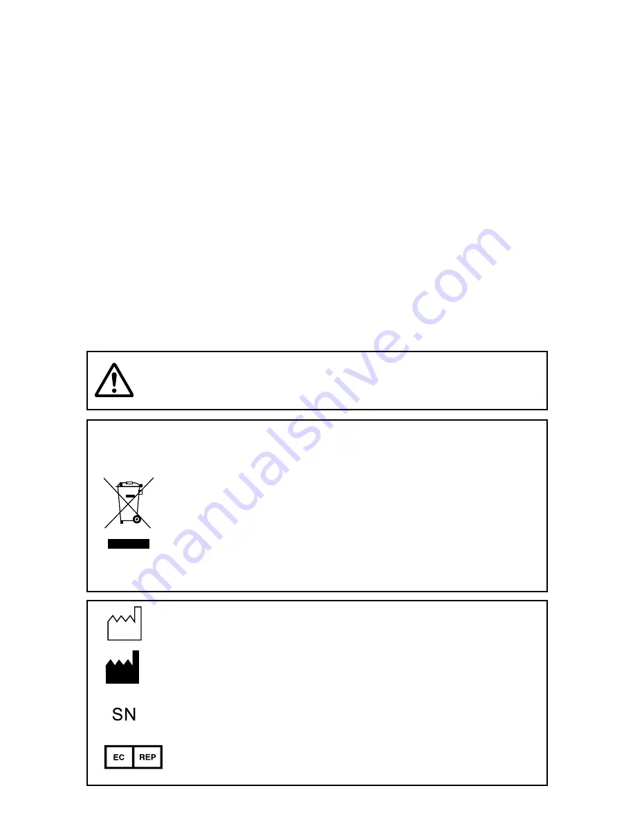
Your MITSUBISHI ELECTRIC product is designed and manufactured with 
high quality materials and components which can be recycled and reused.
This symbol means that electrical and electronic equipment, at their end-of-
life, should be disposed of separately from your household waste.
Please, dispose of this equipment at your local community waste collection/
recycling centre.
In the European Union there are separate collection systems for used electri-
cal and electronic product.
Please, help us to conserve the environment we live in! 

Note: This symbol mark is for EU countries only.
This symbol mark is according to the directive 2002/96/EC Article 10 Information for 
users and Annex IV.

WARNING:

The socket outlet shall be installed near the equipment and 
shall be easily accessible.

:  Manufactured on : to be combined with date code YYYY-MM

: Manufacturers 

Identi

fi

 cation (name address)

: Serial 

number

:  Authorised representative in the European Community

Содержание CP-31W

Страница 1: ...DEUTSCH FRANÇAIS ENGLISH COLORVIDEOCOPYPROCESSOR MODEL CP31W OPERATION MANUAL THISOPERATIONMANUALISIMPORTANT TOYOU PLEASEREADITBEFOREUSINGYOUR COLORVIDEOCOPYPROCESSOR ...

Страница 2: ...his class A digital apparatus complies with Canadian ICES 003 CLASSIFIED BY UNDERWRITERS LABORATORIES INC WITH RESPECT TO ELECTRIC SHOCK FIRE AND MECHANICAL HAZARDS ONLY IN AC CORDANCE WITH UL60601 1 AND CAN CSA C22 2 No 601 1 Indications according to IEC60601 1 1 Functions and intended usage of this product This product receives signals from diagnostic imaging equipment or various signal equip me...

Страница 3: ...s that trouble including equipment malfunction due to static electricity may occur in certain conditions This symbol indicates the possibility that the user may get his her fingers caught in the door slot or other mechanism This symbol indicates the possibility that the user may get injured when he she touches certain areas of the product The Nonionizing radiation symbol The ON OFF symbol indicate...

Страница 4: ... plug at each end The S video cable shall be 1 5 m long or shorter shielded wire or equivalent one with DIN 4P plug at each end This product is to be employed with medical equipment just for reference purpose not for medical diagnostic purpose Your MITSUBISHI ELECTRIC product is designed and manufactured with high quality materials and components which can be recycled and reused This symbol means ...

Страница 5: ...he necessary work for installation maintenance or inspection should be performed under the above mentioned conditions 4 It is recommended that all staff involved in the work in which they may touch the areas identified with the ESD warning symbol should receive an explanation of the ESD warning symbol and training on the ESD precautionary procedures 5 Required minimum contents in the explanation a...

Страница 6: ...000 4 11 Power frequency 50 60 Hz magnetic field EN 61000 4 8 EN 60601 test level 6 kV contact 8 kV air 2 kV for power supply lines 1 kV for input output lines 1 kV line s to line s 2 kV line s to earth 5 UT 95 dip in UT for 0 5 cycle 40 UT 60 dip in UT for 5 cycles 70 UT 30 dip in UT for 25 cycles 5 UT 95 dip in UT for 5 sec 3 A m Electromagnetic environment guidance Floors should be wood concret...

Страница 7: ... fixed RF transmitters as determined by an electromagnetic site survey a should be less than the compliance level in each frequency range b Interference may occur in the vicinity of equipment marked with the following symbol Compliance level 3 Vrms 3 V m NOTE1 At 80 MHz and 800 MHz the higher frequency range applies NOTE2 These guidelines may not apply in all situations Electromagnetic propagation...

Страница 8: ...ng the equation applicable to the frequency of the transmitter where P is the maximum output power rating of the transmitter in watts W according to the transmitter manufacturer NOTE1 At 80 MHz and 800 MHz the separation distance for higher frequency range applies NOTE2 These guidelines may not apply in all situations Electromagnetic propagation is affected by absorption and reflection from struct...

Страница 9: ...22 Printing 23 29 Before printing 23 24 Memory print Multi image setting 25 27 External remote terminal 1 28 External remote terminal 2 29 Setting the functions 30 45 Menu chart 30 31 Selecting and setting menus 32 PROGRAM menu 33 INPUT menu 33 LAYOUT menu 34 PRINT menu 35 36 COLOR ADJ menu 37 OUTPUT menu 38 SETUP menu 39 45 Toubleshooting 46 51 Indication on the status display countermeasures 46 ...

Страница 10: ...llow it to become pinched or cut If the power cord becomes damaged replace it immediately to avoid shock hazard or electrical fire When the power cord is replaced use the same type as originally supplied it is designed to reduce interference to radio TV reception When unplugging the power cord hold the plug and remove it carefully KEEP THE UNIT DRY DO NOT PLACE WATER OR OTHER LIQUID CONTAINERS ON ...

Страница 11: ...e the power cord supplied with the printer INSTALLATION LOCATIONS MAINTAIN GOOD VENTILATION Ventilation slots and holes are provided on the rear sides and bottom of this unit Place the unit on a hard and level surface and keep a space between the unit and the walls to ensure proper ventilation When installing the unit in a system rack leave space between the unit and the back of the rack SUITABLE ...

Страница 12: ...head like a video head wears out When it is worn it becomes hard to print out fine details of the picture If it occurs consult your dealer about having the head replaced CONNECTING DEVICES Read thoroughly the Safety Notices Cautions and Operating Precautions of the instruction booklets for the other devices connected with the unit CAUTION ON RELOCATING When transporting the unit make sure it is no...

Страница 13: ... the appropriate EN60601 1 and or EN60601 1 1 harmonized national standard The transportation and storage environmental conditions are Temperature 20 C 60 C 4 F 140 F Humidity 30 80 RH Atmospheric pressure 50 kPa 106 kPa Note The above transportation environmental conditions indicate the storage environmental conditions during transport OTHER CAUTIONS Dust or other foreign matter adhering to the p...

Страница 14: ... images and ultrasound diagnostic equipment etc The colour is reproducible for each diagnostic equipment with easy operation Each gamma curve is adjustable for each user flexibly 2 PRINT SIZES ARE AVAILABLE ACCORDING TO THE PURPOSE 2 printing sizes L size max 100 x 148 mm and S size max 100 x 94 mm are selectable MULTI PRINT FUNCTION BY THE CAPACIOUS FRAME MEMORY As this unit has 8 frame memories ...

Страница 15: ...nt are printed via video and S video interface This printer creates prints electronically mainly in image processing and printing processing not optically or chemically INTENDED USE The color video copy processor CP31W is intended for use as a hard copy device for an image generated by a diagnostic imaging equipment This product is intended to be used together with medical equipment and to be used...

Страница 16: ...1W OPERATION MANUAL THISOPERATIONMANUALISIMPORTANT TOYOU PLEASEREADITBEFOREUSINGYOUR COLORVIDEOCOPYPROCESSOR VIDEOSTAMPANTE A COLORI MODELLO CP31W MANUALE DʼUSO SI PREGADI LEGGERE ATTENTAMEMTE ILPRESENTE MANUALE DʼUSO PRIMA DI UTILIZZARE LAVIDEOSTAMPANTE ACOLORI Power cords Paper cassette UNPACKING UNPACKING Unwrap the packing NOTE When you lift up this unit do not insert your hand to the print ou...

Страница 17: ... 8 6 15 16 17 18 STATUS DISPLAY FEATURES FUNCTIONS DIMMER BUTTON This button controls the brightness of the print outlet illumination that is lit on the photo the button also controls the brightness of the print status indicator When this button is pushed and held the remaining amount of ink ribbon on the status indicator display is reset MODE BUTTON Each time this button is pushed the light of th...

Страница 18: ...the upper part of the paper cassette Ink ribbon remain ing amount STATUS DISPLAY RIBBON INDICATOR This indicator illuminates for ink ribbon notification See page 46 PAPER INDICATOR This indicator illuminates or blinks for paper notification See page 46 ALARM INDICATOR This indicator illuminates for error conditions See page 46 STATUS INDICATOR This indicator shows the remaining amount of the ink r...

Страница 19: ...displaying menu the menu is closed See page 30 BUTTONS Use to set the menu Values are increased decreased and the cursor position is changed with these four buttons These buttons are also used to select one of memorized images Q TY BUTTON Use to set the number of copies to be printed The set number of copies is displayed on the monitor When this button is pressed the number of prints changes 1 2 t...

Страница 20: ...otential of the device connected to the unit Be sure to make this connection for safety purpose RS 232C PORT Use these terminals to connect this unit to a device equipped with RS 232C interface See pages 16 17 FEATURES FUNCTIONS REMOTE TERMINAL 1 STEREO JACK Memorizing images is available by the remote signal inputted through this terminal It is necessary to make a circuit for remote control unit ...

Страница 21: ...to check the images to be printed and the images stored in memory The following examples show the connections with a video signal S video signal and RS 232C equipment Connect with the necessary signal equipment NOTE Cables for connection are not supplied with this unit Use video cable of 2 m or less or S video cable of 1 5 m or less in length 13 CONNECTIONS PRECAUTIONS FEATURES PREPARATION TROUBLE...

Страница 22: ...TIONS Make sure to turn off the power before connecting example CONNECTION WITH A MONITOR To VIDEO OUT terminal VIDEO To VIDEO IN terminal To S VIDEO OUT terminal S VIDEO To S VIDEO IN terminal Monitor VCP 14 ...

Страница 23: ...NNECTION WITH VIDEO OR S VIDEO SIGNAL EQUIPMENT To VIDEO IN terminal VIDEO VCP VIDEO signal equipment To VIDEO OUT terminal CONFORTABLE LD PLAYER DP L2000 To S VIDEO IN terminal S VIDEO To S VIDEO OUT terminal VCP S VIDEO signal equipment 15 CONNECTIONS PRECAUTIONS FEATURES PREPARATION TROUBLE SHOOTING OTHERS PRINTING ADJUSTMENTS ...

Страница 24: ...32C EQUIPMENT To RS 232C terminal RS 232C To RS 232C terminal VCP Equipment with RS 232C RS 232C TERMINAL SIGNAL Pin number 1 13 14 25 Pin No Signal line name Description Directions 1 FG Protective Earth 2 TXD Transmitted data Output 3 RXD Received data Input 4 RTS Request to send Output 5 CTS Clear to send Input 6 DSR Data set ready Input 7 GND Signal ground Earth 20 DTR Data terminal ready Outpu...

Страница 25: ...bit length 1 Transmission order Sent from LSB Baud rate bit sec 1200 2400 4800 9600 19200 Signal Pin No Pin No Signal FG 1 1 FG TXD 2 2 TXD RXD 3 3 RXD RTS 4 4 RTS CTS 5 5 CTS DSR 6 6 DSR DTR 20 20 DTR GND 7 7 GND example 1 Computer D sub 25 pin RS 232C connection Cable Crossover cable DB25 DB25 Signal Pin No Pin No Signal RXD 2 2 TXD TXD 3 3 RXD DTR 4 6 DSR SG 5 7 GND DSR 6 20 DTR RTS 7 5 CTS CTS...

Страница 26: ... signal S VIDEO Image being displayed memory image Program number being selected 1 Input signal setting FRAME FIELD FRAME Multi image setting 4 image Number of frames in which the image is memorized 2 MENU DISPLAY EXAMPLE Number of prints Program number FRAME FIELD Status of image memorization Multi image setting Input signal Image 2h5 13 3 4 7 0 03 Monitor CONNECTIONS 18 ...

Страница 27: ... paper cassette to the size of the paper to be loaded Do not force paper that is too long or too wide into the paper cassette NOTE Use the paper cassette designed for this unit only Remove the tray cover of the paper cassette Adjust the paper cassette to secure the paper Raise the plate in the cassette to use S size paper Keep the plate laid flat to use L size paper Take the print paper out of the...

Страница 28: ...an load only one package of print paper supplied as paper ink ribbon set Set the tray cover onto the paper cassette Load the paper cassette in the printer When using L size paper raise the stopper on the tray cover CAUTION Do not put your hand inside the product from the paper cassette loading slot or ribbon cartridge loading slot This product has mechanical parts switches and rollers and parts th...

Страница 29: ...ibbon cartridge into the ribbon cartridge loading slot Be sure to hold the handle Insert the ribbon cartridge in the direction of the arrow with the marking of TOP SIDE up The installation of print paper and ribbon cartridge is completed NOTE Do not leave more than 15 sheets of print paper on the print outlet Be sure to install the paper cassette properly If it is not installed properly a paper ja...

Страница 30: ...e of wrong combination may cause malfunction AFTER PRINTING When the printed paper is touched with a wet hand the print may be discolored Fading may occur if the print face is exposed to organic chemical agents which may affect print paper e g alcohol ester ketene based Fading will be accelerated upon contact with PVC based materials e g adhesive tapes rubber erasers etc Do not put a print back in...

Страница 31: ...image FRAME image Press the MENU button on the control panel A menu is displayed Press the or button to display the INPUT menu Press the or button to select the FRAME FIELD Press the or button to select FRAME or FIELD Press the MENU button The setting is memorized and the source image is displayed MENU button buttons 13 165 13 0 065 4 561 6 3 563 165 4 7 0 3 5 44 0 53 45 0 03 6 4 31 44 3 3 4 5 1 6...

Страница 32: ... the control panel A menu is displayed Press the or button to display the INPUT menu Press the or button to select the INPUT Press the or button to select VIDEO or S VIDEO Press the MENU button The setting is memorized and the source image is displayed MENU button buttons 13 165 13 0 065 4 561 6 3 563 165 4 7 0 3 5 44 0 53 45 0 03 6 4 31 44 3 3 4 5 1 650 5 3 13 165 13 0 065 4 561 6 3 563 165 7 0 3...

Страница 33: ...wn on the monitor When displaying the image from the connected equipment LIVE is shown An image can be stored into memory while printing but not in the memory page currently being printed MEMORIZING AND PRINTING AN IMAGE Display the image which you wish to print Press the MEM PAGE button on the control panel to select a page to memorize an image Press the MEMORY button The image will be memorized ...

Страница 34: ...nitor screen Print example 2 1 4 2 1 1 1 2 3 4 MULTI 4 8 2 S L 1 2 1 2 3 4 1 MULTI PRINT MULTI PRINT is the function of 2 or 4 image print on a sheet Use LAYOUT menu for setting See the above table for the print examples For the setting see page 34 PRINTING 26 ...

Страница 35: ...itor will be counted down every time one sheet is printed When printing is completed the counter will be reset to the original set number This will not reset when turning off the power It will not be reset to 1 If you wish to stop printing after completing the current printing press the CLEAR STOP button After the counter is reset to 1 and the print of the current page is completed the continuous ...

Страница 36: ...ory When the signal has been LOW for 15 ms or more the image is stored in memory See page 40 3 BUSY1 Refer to the BUSY LEVEL setting and BUSY 1 2 SELECT setting of REMOTE SET menu See pages 42 44 When the signal from BUSY terminal is received with TTL level keep the following IOL 2 mA or less IOH 1 mA or less IOL means the current flowing into the unit at Low output IOH means the current flowing o...

Страница 37: ...ng and BUSY 1 2 SELECT setting of REMOTE SET menu See pags 42 44 5 PRINT Print When the signal becomes LOW from HIGH the stored image is printed When the signal has been LOW for 15 ms or more the image is printed 6 Unused 7 Unused 8 DC5V Power supply DC 1 mA Max When the signal from BUSY terminal is received with TTL level keep the following IOL 2 mA or less IOH 1 mA or less IOL means the current ...

Страница 38: ...4 7 0 3 5 44 0 53 45 0 03 6 4 31 44 3 3 4 5 1 650 5 3 13 065 13 0 065 4 561 6 3 563 6 5 4 4 1 3 5 0 03 501 03 0550 03 5 03 3 5 03 104 5 5 3 5 3 13 13 5 0 065 4 561 6 3 563 3 5 0 4 31 44 13 5 0 45 3 3 5 0 5 0 5 3 13 13 0 03 065 4 561 6 3 563 3 5 44 0 53 45 3 5 3 08 6 5 3 13 13 0 065165 4 561 6 3 563 3 5 44 0 53 45 0 03 5 3 13 13 0 065 4 561 6 3 563 4 45 4 5 34 4 5 4 5 3 05 4 5 65 5 4 5 To the next ...

Страница 39: ... 3 410 4 0 3303 3 410 4 34 4 5 13 13 0 065 4 561 6 3 563 03 6 03 1 3 5 0 03 4501 0 03 0 503 0 650 3 0 3 6 3 0 4 5 13 13 0 065 4 561 6 3 563 64 7 08 64 4 5 13 5 64 64 3303 64 0 03 64 0 4530 64 4530 64 3 64 3 05 4 5 13 13 0 065 4 561 6 3 563 13 7 064 3303 5 3 5 45 13 5 5 3 65 5 4 5 13 13 0 065 4 561 6 3 563 4 45 4 5 34 4 5 4 5 3 05 4 5 65 5 4 5 MENU MENU MENU MENU MENU 31 CONNECTIONS PRECAUTIONS FEA...

Страница 40: ...r button to select the menu to set Select the LAYOUT menu Press the button to display the sub menus Press the or button to select the setting or change the value Select the setting among 1 2 and 4 Press the MENU button to return to the normal screen MENU button buttons 13 065 13 0 065 4 561 6 3 563 6 5 4 4 1 3 5 0 03 501 03 0550 03 5 03 3 5 03 104 5 5 3 5 3 13 065 13 0 065 4 561 6 3 563 6 5 4 4 1 ...

Страница 41: ...contour of image Adjustmemt for input signal The value gets smaller the contour gets softer The value gets larger the contour gets reinforced FRAME FIELD Select FRAME for normal use Select FIELD for a picture of quickly moving objects When FIELD is selected the print image will be lower in resolution SIGNAL TYPE Detects NTSC signal and PAL signal AUTO This unit automatically detects NTSC signal or...

Страница 42: ...on of the horizontal importing of the input signal MEMORY LEFT Changes the start position of the vertical importing of the input signal MEMORY RIGHT Changes the end position of the vertical importing of the input signal MEMORY POSI INIT The values of MEMORY TOP MEMORY BOTTOM MEMORY LEFT and MEMORY RIGHT are reset CANCEL When the ENTER button is pressed while CANCEL is selected the settings in the ...

Страница 43: ...ghter LIGHT Adjusts the bright part of the printing image The value gets smaller the image gets darker The value gets larger the image gets lighter COMMENT Selects to display the comment or not OFF Does not print a comment ON Prints a comment When the ENTER button is pressed while selecting ON the menu to make a comment is shown ADJUST The total number of prints settings image size and other setti...

Страница 44: ...cursor position and the letters shift to right DEL Select DEL and press the ENTER button to delete the selected letter The letters shift to left CLEAR Select CLEAR and press the ENTER button to clear the comment CANCEL Select CANCEL and press the ENTER button to go back to the previous comment which has been memorized SAVE EXIT Select SAVE EXIT and press the ENTER button to memorize the comment an...

Страница 45: ...ting image Green is added with and magenta is added with YELLOW BLUE Adjusts blue subcontrast of the printing image Blue is added with and yellow is added with CANCEL When the ENTER button is pressed while CANCEL is selected the settings in the COLOR ADJ menu are return to those before change The changes are not saved 13 13 0 03 065 4 561 6 3 563 3 5 44 0 53 45 3 5 3 08 6 5 3 37 CONNECTIONS PRECAU...

Страница 46: ... and CONTRAST are applied only to the image on the monitor They are not applied to the printed images COLOR Adjusts density of the image on the monitor The colour of the image gets deeper with and lighter with CANCEL When the ENTER button is pressed while CANCEL is selected the settings in the OUTPUT menu are return to those before change The changes are not saved SETTING THE FUNCTIONS 13 13 0 065...

Страница 47: ...hen a ribbon cartridge is loaded after the indication becomes to 00 the indication is reset to the initial value COPY PROGRAM TO The settings of the currently used program are copied to other program by selecting other program and then pressing the ENTER button When CANCEL is selected after selecting the program number the program is not copied even if the ENTER button is pressed INITIALIZE PRG In...

Страница 48: ...omatically prints after memorizing Do not change the setting of MULTI IMAGE after memorizing an image R1 When a signal inputted through a memory key pin No 2 of the remote terminal on the rear panel is switched to low level from high or the MEMORY button on the front panel is pressed for the first time a memory image is displayed Then at the second time a source image is displayed without printing...

Страница 49: ...mages are memorized in all frames in a page MEMORY MONITOR Switches the monitor display between the source image and memory image after memorizing OFF The memorized image is displayed for about 1 second after memorizing then the source image is displayed ON The memorized image is displayed after memorizing PRINT LIVE The memorized image is displayed after memorizing The source image is displayed a...

Страница 50: ...uring stand by mode BUZZER Selects whether the buzzer sounds or not when any button on this unit is pressed OFF Does not sound the buzzer ON Sounds the buzzer REMOTE SET Selecting the remote signal etc BUSY LEVEL Selects the level of BUSY signal from the remote terminals 1 and 2 on the rear panel LOW This unit cannot accept the remote input signal when the signal is LOW HIGH This unit cannot accep...

Страница 51: ...le this unit outputs BUSY1 and BUSY2 signals STROBE1 OFF This unit does not output a trigger signal for strobe BUSY1 When memorizing an image this unit outputs a trigger signal 1 for strobe through BUSY1 BUSY2 When memorizing an image this unit outputs a trigger signal 1 for strobe through BUSY2 BUSY1 2 When memorizing an image this unit outputs a trigger signal 1 for strobe through BUSY1 and BUSY...

Страница 52: ...bbon reaches to the value set by the REMAINING Q TY menu this unit outputs the BUSY1 signal to inform the remaining of ink ribbon BUSY2 When the remaining amount of the ink ribbon reaches to the value set by the REMAINING Q TY menu this unit outputs the BUSY2 signal BUSY1 2 When the remaining amount of the ink ribbon reaches to the value set by the REMAINING Q TY menu this unit outputs the BUSY 1 ...

Страница 53: ...emorizing The numbers in the above figures are just references The timing may be different according to the setting UTILITY SET PREVIOUS ERROR This function displays the most recent types of error TEST PRINT A test printing is carried out 13 13 0 065 4 561 6 3 563 13 7 064 3303 5 3 5 45 13 5 5 3 65 5 4 5 45 CONNECTIONS PRECAUTIONS FEATURES PREPARATION TROUBLE SHOOTING OTHERS PRINTING ADJUSTMENTS ...

Страница 54: ...STATUS DISPLAY COUNTERMEASURES TROUBLESHOOTING Status indicator RIBBON PAPER ALARM Error messages The ribbon cartridge is not loaded Ink ribbon has run out The paper cassete is not loaded Paper has run out Remove paper from the printer outlet Flap is open Access cover is open Wrong type of ribbon cartridge Wrong size of paper type Remove the paper cassette check the paper Paper jam Access cover is...

Страница 55: ...aper of wrong size is loaded Use the ribbon cartridge and print paper supplied in the same package Paper misfeed Unload the paper cassette and load it again Paper jam occurs Refer to OVERCOMING PAPER JAMS The access cover opens during printing Turn off the power close the access cover and then turn on the power again Paper jam occurs A mechanical error occurs Turn off the power and then turn it on...

Страница 56: ...s cover to remove the jammed paper NOTE Turn the dial in the direction of the arrow Never turn it in the opposite direction It may cause malfunction Contact your dealer if you can not clear the paper jam per above instruction Close the access cover Load the paper cassette Load the ribbon cartridge Remove slack the ink ribbon Hold the handle to load the cartridge CAUTION Do not put your hand inside...

Страница 57: ...layed on the monitor screen Press the MONITOR button to display the source image LIVE The image is not stored in memory Are the images being printed with full memorized memory page Press the CLEAR STOP button on the control panel after completing printing Then store the image in the memory again Is the memory full in the status of PAGE INCREMENT OFF or AUTO CLEAR OFF Store the image in the memory ...

Страница 58: ...oaded Is the power of this unit turned on Is another ribbon cartridge already loaded in this unit Check the status The colour or picture quality is different Is the colour of the image stored in the memory between the memorized image and the adjusted printed image Adjust the colour of the image stored in the memory with COLOR ADJ menu Refer to page 37 The picture quality is different between Is th...

Страница 59: ... adhesive cellophane tape on the center of the ink ribbon REPAIRING A TORN INK RIBBON Wind the gear in the direction of the arrow so that the cellophane tape is not seen and the ink ribbon is stretched taut Install the repaired ribbon cartridge in the printer 51 CONNECTIONS PRECAUTIONS FEATURES PREPARATION TROUBLE SHOOTING OTHERS PRINTING ADJUSTMENTS ...

Страница 60: ...EANING Clean the thermal head using the cleaning kit for CP31 option Model CS30 to maintain stable printer operation and extend the printer s life Please ask your dealer about the cleaning kit CLEANING 52 ...

Страница 61: ... Composite video 1 BNC type connectors S video 1 S video terminal Input Output terminal RS 232C D SUB 25 pin Remote terminal Mini Din 8 pin stereo mini jack Input frequency H frequency 15 734 kHz V frequency 60 Hz NTSC H frequency 15 625 kHz V frequency 50 Hz PAL Power supply 120 220 240 V 50 60 Hz Power consumption 1 7 A AC120 V 50 60 Hz during printing 0 3 A when not printing 1 0 A AC220 240 V 5...

Страница 62: ...size 40 Color print 4 packs contained with surface lamination CLEANING KIT FOR CP31 Model CS30 SERVICE INFORMATION Before requesting service please review this operation manual to correct minor complaints If you are unable to correct the problem consult your MITSUBISHI Dealer or MITSUBISHI Service Department DO NOT ADJUST ANY CONTROLS NOT DESCRIBED IN THIS OPERATION MANUAL DO NOT REMOVE THE PROTEC...

Отзывы: